Palo Alto Networks Next-Generation Firewall
This tutorial includes the steps required to configure IPsec tunnels to connect a Palo Alto Networks Next-Generation Firewall (NGFW) to Cloudflare Magic WAN through a Layer 3 deployment.
Software version tested
- PAN-OS 9.1.14-h4
Use Cases
- Magic WAN: Connecting two or more locations with RFC-1918 private non-routable address space.
- Magic WAN with Cloudflare Zero Trust (Gateway egress): Same as Magic WAN, with the addition of outbound Internet access from Magic WAN protected sites egressing the Cloudflare edge network.
Prerequisites
This tutorial assumes you have a standalone NGFW with two network interfaces:
- One in a trust security zone (
Trust_L3_Zone) with an RFC-1918 non-Internet routable IP address (internal network); - And the other in an untrust security zone (
Untrust_L3_Zone) with a legally routable IP address (Internet facing).
Additionally, there must be a default gateway set on the Virtual Router (default) pointing to the router of your Internet service provider(s).
Environment
The following IP addresses are used throughout this tutorial. Any legally routable IP addresses have been replaced with IPv4 Address Blocks Reserved for Documentation (
RFC5737) addresses within the 203.0.113.0/24 subnet.
| Description | Address | Address |
|---|---|---|
| NGFW external interface | 203.0.113.254/24 |
|
| NGFW internal interface | 10.1.100.254/24 |
|
| Local trust subnet (LAN) | 10.1.100.0/24 |
|
| NGFW tunnel interface 01 | 10.252.2.26/31 (Cloudflare side) |
10.252.2.27/31 (NGFW side) |
| NGFW tunnel interface 02 | 10.252.2.28/31 (Cloudflare side) |
10.252.2.29/31 (NGFW side) |
| Magic WAN Anycast IP | 162.159.66.164 |
172.64.242.164 |
| Magic WAN health check Anycast IP | 172.64.240.253 |
172.64.240.254 |
| VLAN0010 - remote Magic WAN site | 10.1.10.0/24 |
|
| VLAN0020 - remote Magic WAN site | 10.1.20.0/24 |
Cloudflare Magic WAN
Magic IPsec Tunnels
Use the Cloudflare dashboard or API to configure two IPsec Tunnels. The settings mentioned in Add IPsec tunnels below are used for the IPsec tunnels referenced throughout the remainder of this guide.
These are the target IP addresses for bidirectional tunnel health checks:
172.64.240.253: Use with the primary IPsec tunnel.172.64.240.254: Use with the secondary IPsec tunnel.
Add IPsec tunnels
-
Follow the Add tunnels instructions to create the required IPsec tunnels with the following options:
- Tunnel name:
SFO_IPSEC_TUN01 - Interface address:
10.252.2.96/31 - Customer endpoint:
203.0.113.254 - Cloudflare endpoint:
162.159.66.164 - Health check rate: Low (default value is Medium)
- Health check type: Reply
- Health check target: Custom (default is Default)
- Target address:
172.64.240.253
- Tunnel name:
-
Select Add pre-shared key later > Add tunnels.
-
Repeat the process to create a second IPsec tunnel with the following options:
- Tunnel name:
SFO_IPSEC_TUN02 - Interface address:
10.252.2.98/31 - Customer endpoint:
203.0.113.254 - Cloudflare endpoint:
172.64.242.164 - Health check rate: Low (default value is Medium)
- Health check type: Reply
- Health check target: Custom (default is Default)
- Target address:
172.64.240.254
- Tunnel name:
Generate Pre-shared keys
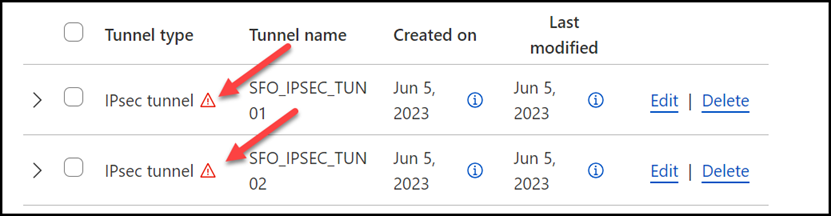
When you create IPsec tunnels with the option Add pre-shared key later, the Cloudflare dashboard will show you a warning indicator:
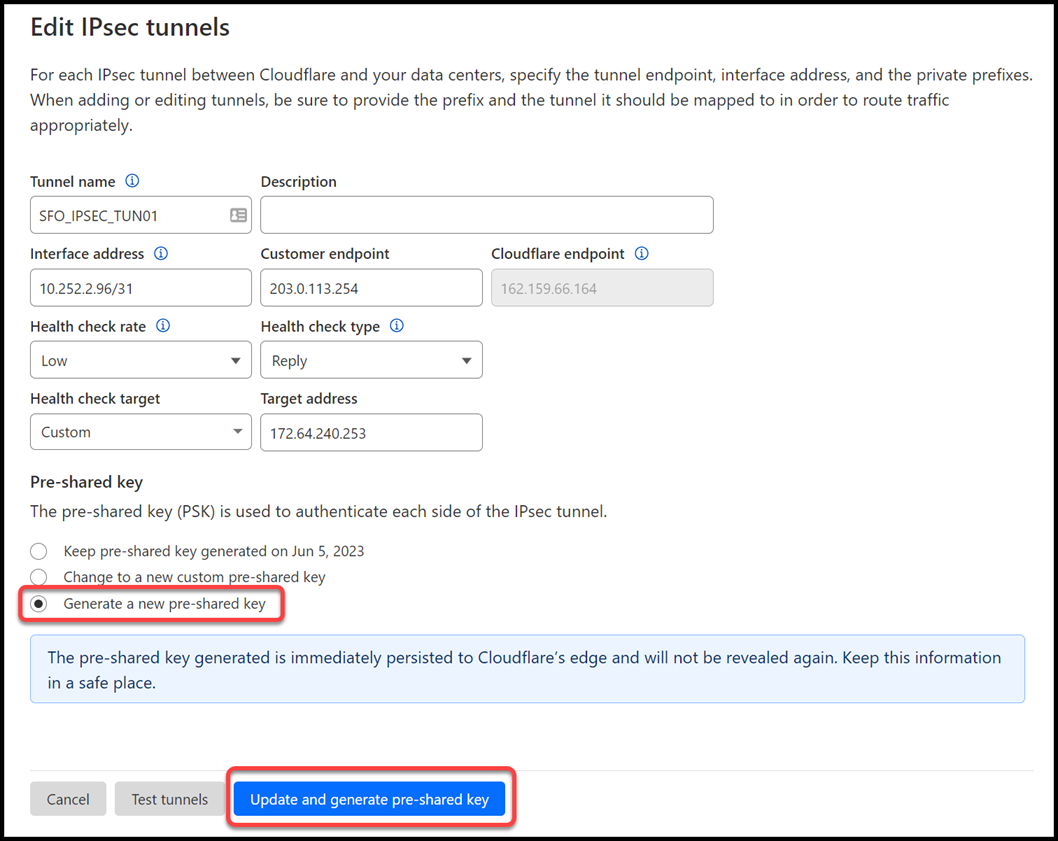
- Select Edit to edit the properties of each tunnel.
- Select Generate a new pre-shared key > Update and generate pre-shared key.
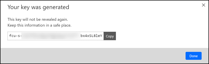
- Copy the pre-shared key value for each of your IPsec tunnels, and save these values somewhere safe. Then, select Done.
IPsec identifier - FQDN (Fully Qualified Domain Name)
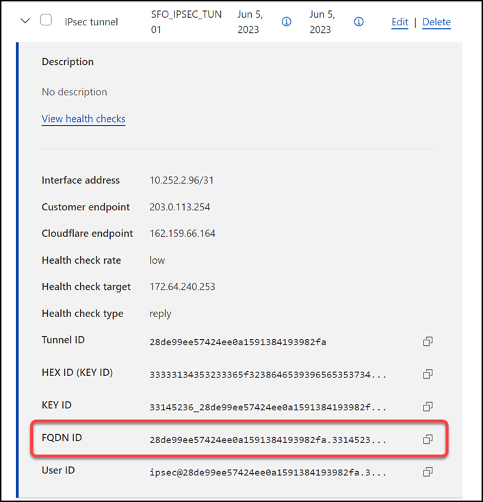
After creating your IPsec tunnels, the Cloudflare dashboard will list them under the Tunnels tab. Select the arrow (>) on each of your IPsec tunnel to collect the FQDN ID value from each of them. The FQDN ID value will be required when configuring IKE Phase 1 on the Palo Alto Networks Next-Generation Firewall.
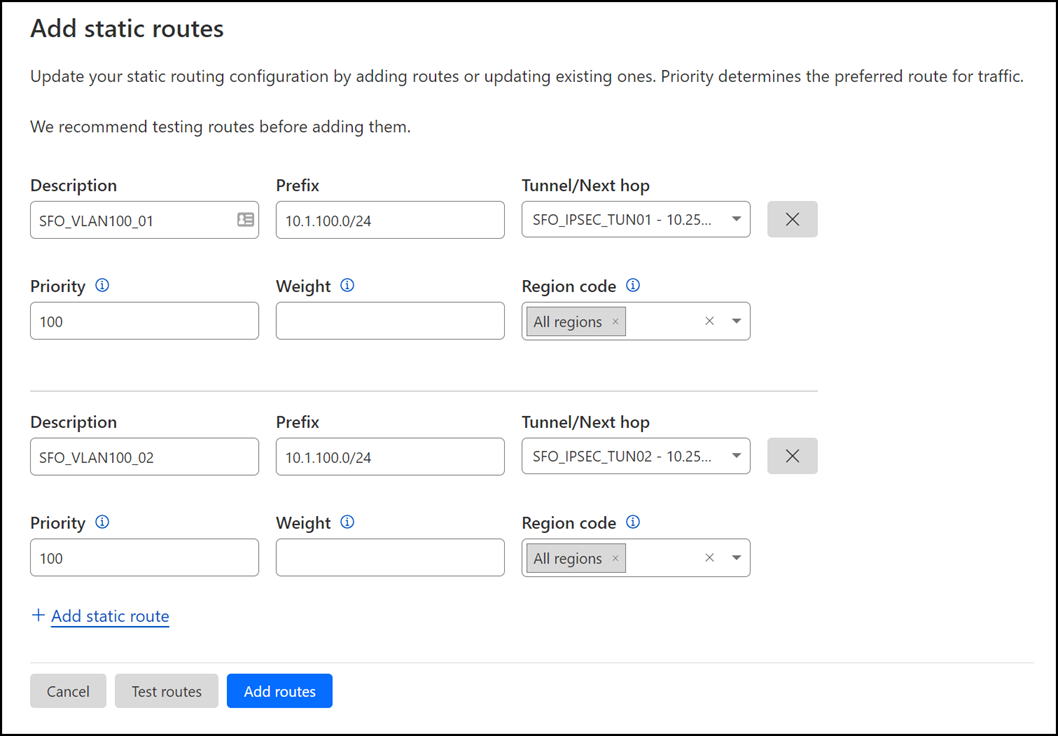
Magic Static Routes
If you refer to the Environment section, you will notice there is one subnet within Trust_L3_Zone: 10.1.100.0/24.
Create a static route for each of the two IPsec tunnels configured in the previous section, with the following settings (settings not mentioned here can be left with their default settings):
Tunnel 01
- Description:
SFO_VLAN100_01 - Prefix:
10.1.100.0/24 - Tunnel/Next hop:
SFO_IPSEC_TUN01
Tunnel 02
- Description:
SFO_VLAN100_02 - Prefix:
10.1.100.0/24 - Tunnel/Next hop:
SFO_IPSEC_TUN02
Palo Alto Networks Next-Generation Firewall
Tags
While Tags are optional, they can greatly improve object and policy visibility. The following color scheme was implemented in this configuration:
| Tag | Color |
|---|---|
Trust_L3_Zone |
Green |
Untrust_L3_Zone |
Red |
Cloudflare_L3_Zone |
Orange |
Use the Palo Alto Networks Next-Generation Firewall command-Line to set the tags:
Objects
The use of Address and Address Group objects wherever possible is strongly encouraged. These objects ensure that configuration elements that reference them are defined accurately and consistently.
Any configuration changes should be applied to the objects and will automatically be applied throughout the remainder of the configuration.
Address Objects
| Name | Type | Address | Tags |
|---|---|---|---|
CF_Health_Check_Anycast_01 |
IP Netmask | 172.64.240.253 |
Cloudflare_L3_Zone |
CF_Health_Check_Anycast_02 |
IP Netmask | 172.64.240.254 |
Cloudflare_L3_Zone |
CF_Magic_WAN_Anycast_01 |
IP Netmask | 162.159.66.164 |
Cloudflare_L3_Zone |
CF_Magic_WAN_Anycast_02 |
IP Netmask | 172.64.242.164 |
Cloudflare_L3_Zone |
CF_MWAN_IPsec_VTI_01_Local |
IP Netmask | 10.252.2.27/31 |
Cloudflare_L3_Zone |
CF_MWAN_IPsec_VTI_01_Remote |
IP Netmask | 10.252.2.26 |
Cloudflare_L3_Zone |
CF_MWAN_IPsec_VTI_02_Local |
IP Netmask | 10.252.2.29/31 |
Cloudflare_L3_Zone |
CF_MWAN_IPsec_VTI_02_Remote |
IP Netmask | 10.252.2.28 |
Cloudflare_L3_Zone |
CF_WARP_Client_Prefix |
IP Netmask | 100.96.0.0/12 |
Cloudflare_L3_Zone |
Cloudflare_IPv4_01 |
IP Netmask | 173.245.48.0/20 |
Cloudflare_L3_Zone |
Cloudflare_IPv4_02 |
IP Netmask | 103.21.244.0/22 |
Cloudflare_L3_Zone |
Cloudflare_IPv4_03 |
IP Netmask | 103.22.200.0/22 |
Cloudflare_L3_Zone |
Cloudflare_IPv4_04 |
IP Netmask | 103.31.4.0/22 |
Cloudflare_L3_Zone |
Cloudflare_IPv4_05 |
IP Netmask | 141.101.64.0/18 |
Cloudflare_L3_Zone |
Cloudflare_IPv4_06 |
IP Netmask | 108.162.192.0/18 |
Cloudflare_L3_Zone |
Cloudflare_IPv4_07 |
IP Netmask | 190.93.240.0/20 |
Cloudflare_L3_Zone |
Cloudflare_IPv4_08 |
IP Netmask | 188.114.96.0/20 |
Cloudflare_L3_Zone |
Cloudflare_IPv4_09 |
IP Netmask | 197.234.240.0/22 |
Cloudflare_L3_Zone |
Cloudflare_IPv4_10 |
IP Netmask | 198.41.128.0/17 |
Cloudflare_L3_Zone |
Cloudflare_IPv4_11 |
IP Netmask | 162.158.0.0/15 |
Cloudflare_L3_Zone |
Cloudflare_IPv4_12 |
IP Netmask | 104.16.0.0/13 |
Cloudflare_L3_Zone |
Cloudflare_IPv4_13 |
IP Netmask | 104.24.0.0/14 |
Cloudflare_L3_Zone |
Cloudflare_IPv4_14 |
IP Netmask | 172.64.0.0/13 |
Cloudflare_L3_Zone |
Cloudflare_IPv4_15 |
IP Netmask | 131.0.72.0/22 |
Cloudflare_L3_Zone |
Internet_L3_203-0-113-254--24 |
IP Netmask | 203.0.113.254/24 |
Untrust_L3_Zone |
VLAN0010_10-1-10-0--24 |
IP Netmask | 10.1.10.0/24 |
Cloudflare_L3_Zone |
VLAN0020_10-1-20-0--24 |
IP Netmask | 10.1.20.0/24 |
Cloudflare_L3_Zone |
VLAN0100_10-1-100-0--24 |
IP Netmask | 10.1.100.0/24 |
Trust_L3_Zone |
VLAN0100_L3_10-1-100-254--24 |
IP Netmask | 10.1.10.254/24 |
Trust_L3_Zone |
Use the Palo Alto Networks Next-Generation Firewall command-Line to set the objects:
Address Group object
The Address Group object used in this configuration provides a single object representation of the entire Cloudflare IPv4 public address space.
| Name | Type | Addresses | Tags |
|---|---|---|---|
Cloudflare_IPv4_Static_Grp |
Static | Cloudflare_IPv4_01 |
Cloudflare_L3_Zone |
Cloudflare_IPv4_Static_Grp |
Static | Cloudflare_IPv4_02 |
Cloudflare_L3_Zone |
Cloudflare_IPv4_Static_Grp |
Static | Cloudflare_IPv4_03 |
Cloudflare_L3_Zone |
Cloudflare_IPv4_Static_Grp |
Static | Cloudflare_IPv4_04 |
Cloudflare_L3_Zone |
Cloudflare_IPv4_Static_Grp |
Static | Cloudflare_IPv4_05 |
Cloudflare_L3_Zone |
Cloudflare_IPv4_Static_Grp |
Static | Cloudflare_IPv4_06 |
Cloudflare_L3_Zone |
Cloudflare_IPv4_Static_Grp |
Static | Cloudflare_IPv4_07 |
Cloudflare_L3_Zone |
Cloudflare_IPv4_Static_Grp |
Static | Cloudflare_IPv4_08 |
Cloudflare_L3_Zone |
Cloudflare_IPv4_Static_Grp |
Static | Cloudflare_IPv4_09 |
Cloudflare_L3_Zone |
Cloudflare_IPv4_Static_Grp |
Static | Cloudflare_IPv4_10 |
Cloudflare_L3_Zone |
Cloudflare_IPv4_Static_Grp |
Static | Cloudflare_IPv4_11 |
Cloudflare_L3_Zone |
Cloudflare_IPv4_Static_Grp |
Static | Cloudflare_IPv4_12 |
Cloudflare_L3_Zone |
Cloudflare_IPv4_Static_Grp |
Static | Cloudflare_IPv4_13 |
Cloudflare_L3_Zone |
Cloudflare_IPv4_Static_Grp |
Static | Cloudflare_IPv4_14 |
Cloudflare_L3_Zone |
Cloudflare_IPv4_Static_Grp |
Static | Cloudflare_IPv4_15 |
Cloudflare_L3_Zone |
Use the Palo Alto Networks Next-Generation Firewall command-Line to set the address group object:
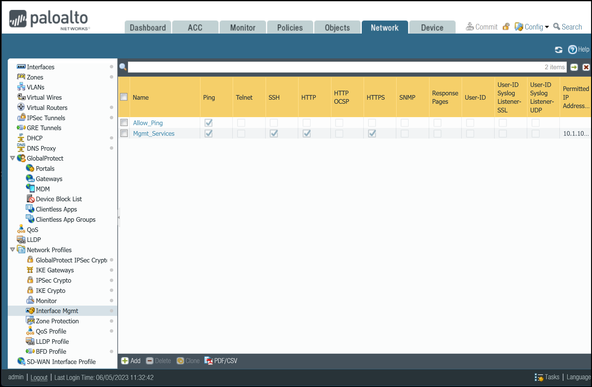
Interface Mgmt - Network Profiles
Interface Mgmt profiles control what traffic is allowed to the firewall, as opposed to through the firewall.
Adding an Interface Mgmt profile to the tunnel interfaces will provide the ability to ping the Virtual Tunnel Interface on your firewall(s).
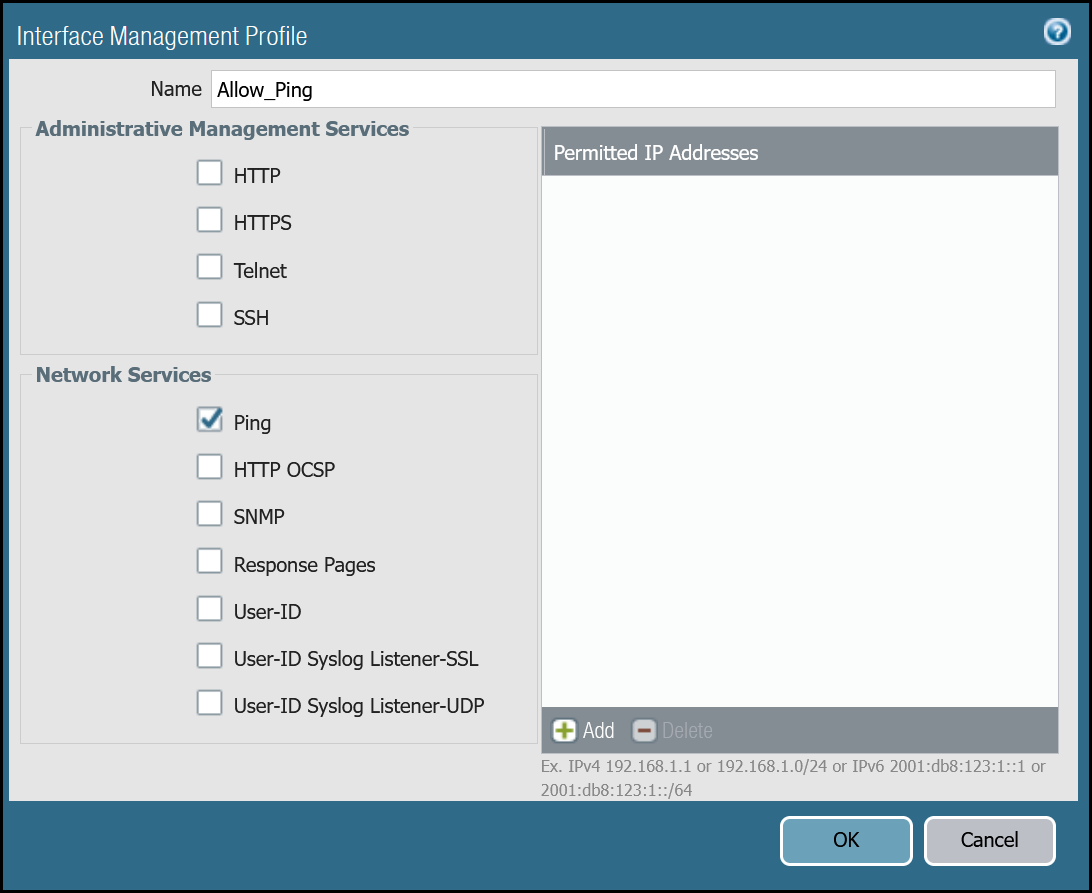
Set up via dashboard
You can define an Interface Management Profile to allow ping from the dashboard:
- Go to Network Profiles > Interface Mgmt.
- In the Network tab select Add.
- Create profiles to allow Ping, and in the Network Services group select Ping.
Set up via command line
You can also use the command line to allow ping:
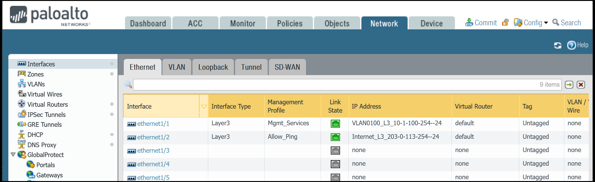
Network Interfaces
Palo Alto Networks Next-Generation Firewall (NGFW) is configured with two Ethernet interfaces:
| Interface | Interface Type | IP Address | Virtual Router |
|---|---|---|---|
| ethernet1/1 | Layer3 | 10.1.100.254/24 |
default |
| ethernet1/2 | Layer3 | 203.0.113.254/24 |
default |
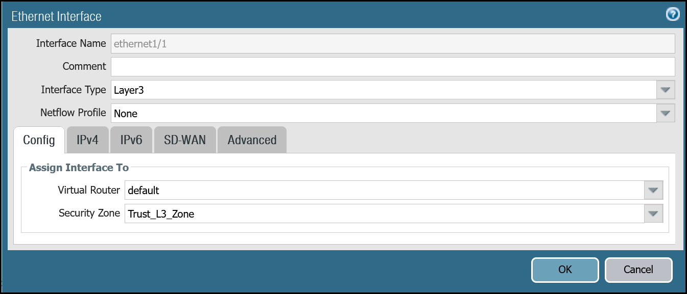
Set up via dashboard
Follow the guidance on the images below to set up the Ethernet interfaces through the dashboard.
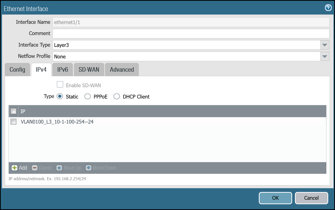
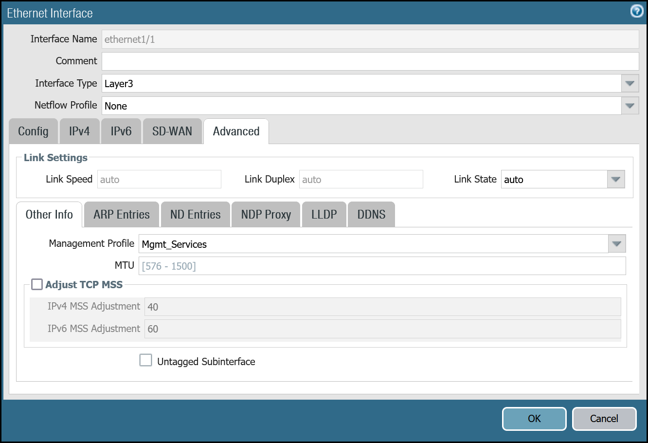
ethernet1/1: Trust_L3_Zone
| Name | Option | Value |
|---|---|---|
| ethernet1/1 | Interface Type | Layer3 |
| Netflow Profile | None | |
| Config tab | Virtual Router | default |
| Security Zone | Trust_L3_Zone | |
| IPv4 tab | Type | Static |
| IP | VLAN0100_L3_10-1-100-254--24 address object |
|
| Advanced tab | Management Profile | Mgmt_Services |
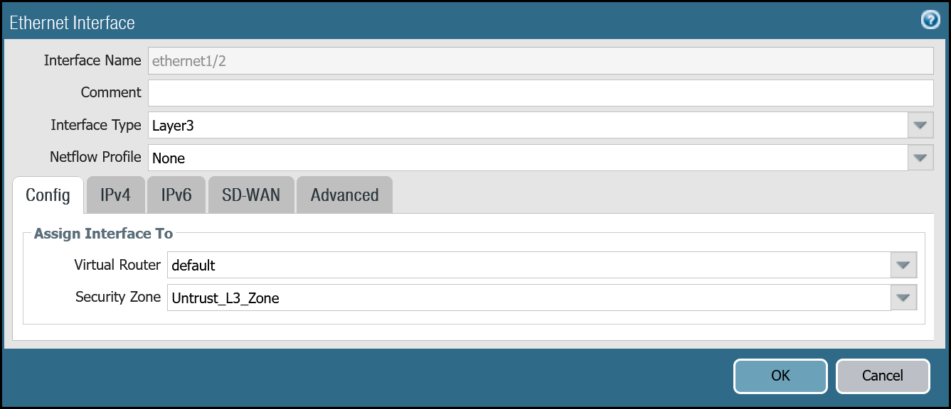
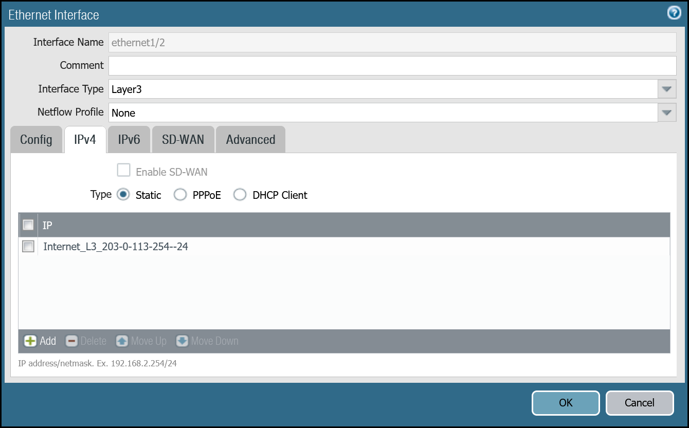
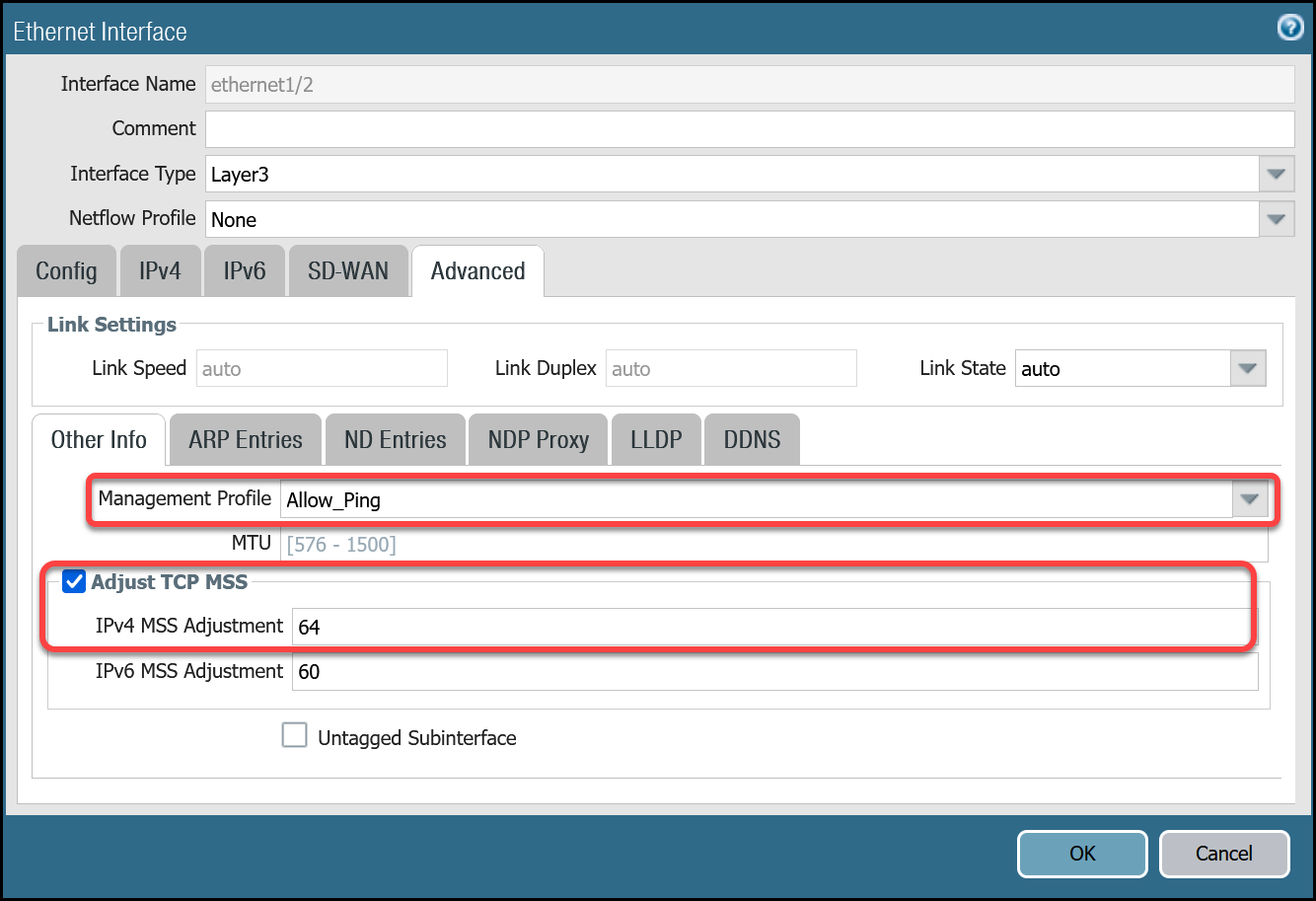
ethernet1/2: Untrust_L3_Zone
| Name | Option | Value |
|---|---|---|
| ethernet1/2 | Interface Type | Layer3 |
| Netflow Profile | None | |
| Config tab | Virtual Router | default |
| Security Zone | Untrust_L3_Zone | |
| IPv4 tab | Type | Static |
| IP | Internet_L3_203-0-113-254--24 address object |
|
| Advanced tab | Management Profile | Allow_Ping |
| MTU | 576 - 1500 |
|
| Adjust TCP MSS | Enable | |
| IPv4 MSS Adjustment | 64 |
After setting up your Ethernet interfaces, they should show up on the overview page:
Set up via command line
You can also use the command line to set up the Ethernet interfaces.
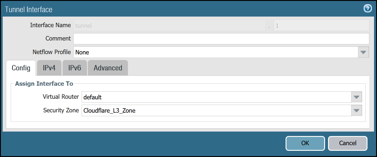
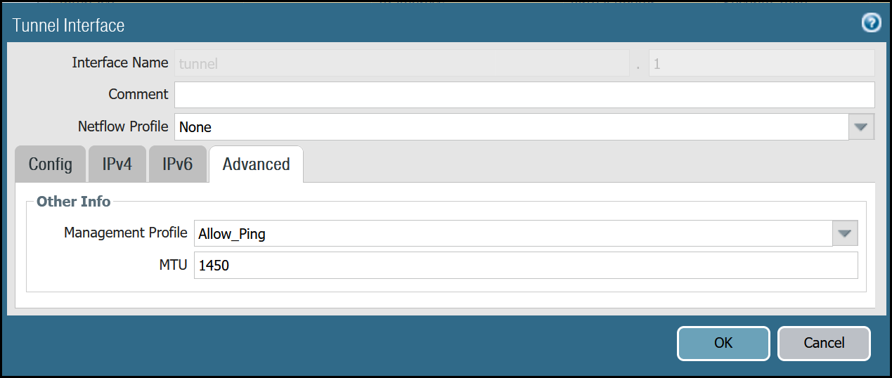
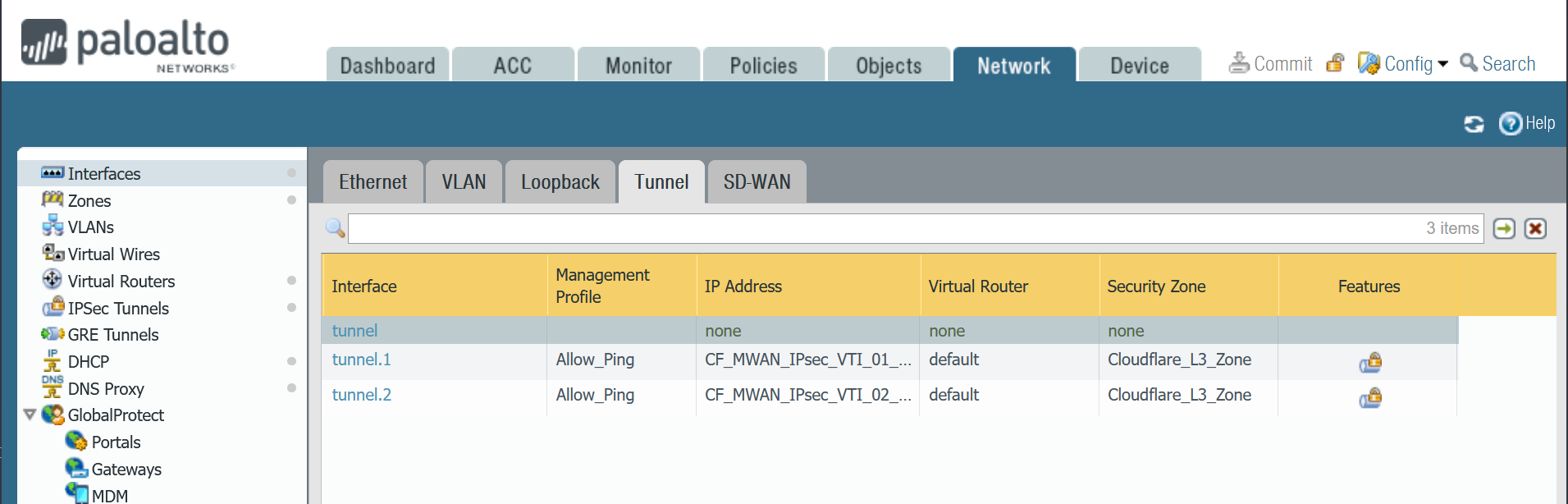
Tunnel interfaces
Establishing IPsec Tunnels to Cloudflare Magic WAN requires two tunnel interfaces - one to each of the two Cloudflare Anycast IP addresses. You also have to ensure that Allow_Ping is bound to both tunnel adapters in Advanced > Managementt Profile.
Review the images below for more information.
Set up via dashboard
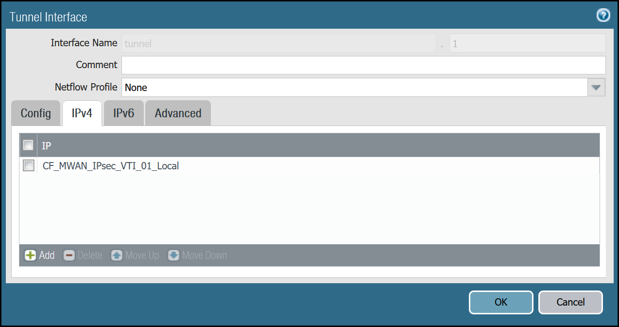
tunnel.1 - Cloudflare_L3_Zone
| Name | Option | Value |
|---|---|---|
| tunnel.1 | Netflow Profile | None |
| Config tab | Virtual Router | default |
| Security Zone | Cloudflare_L3_Zone | |
| IPv4 tab | IP | CF_MWAN_IPsec_VTI_01_Local address object |
| Advanced tab | Management Profile | Allow_Ping |
| MTU | 1450 |
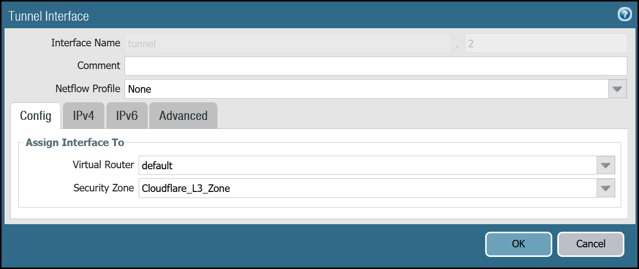
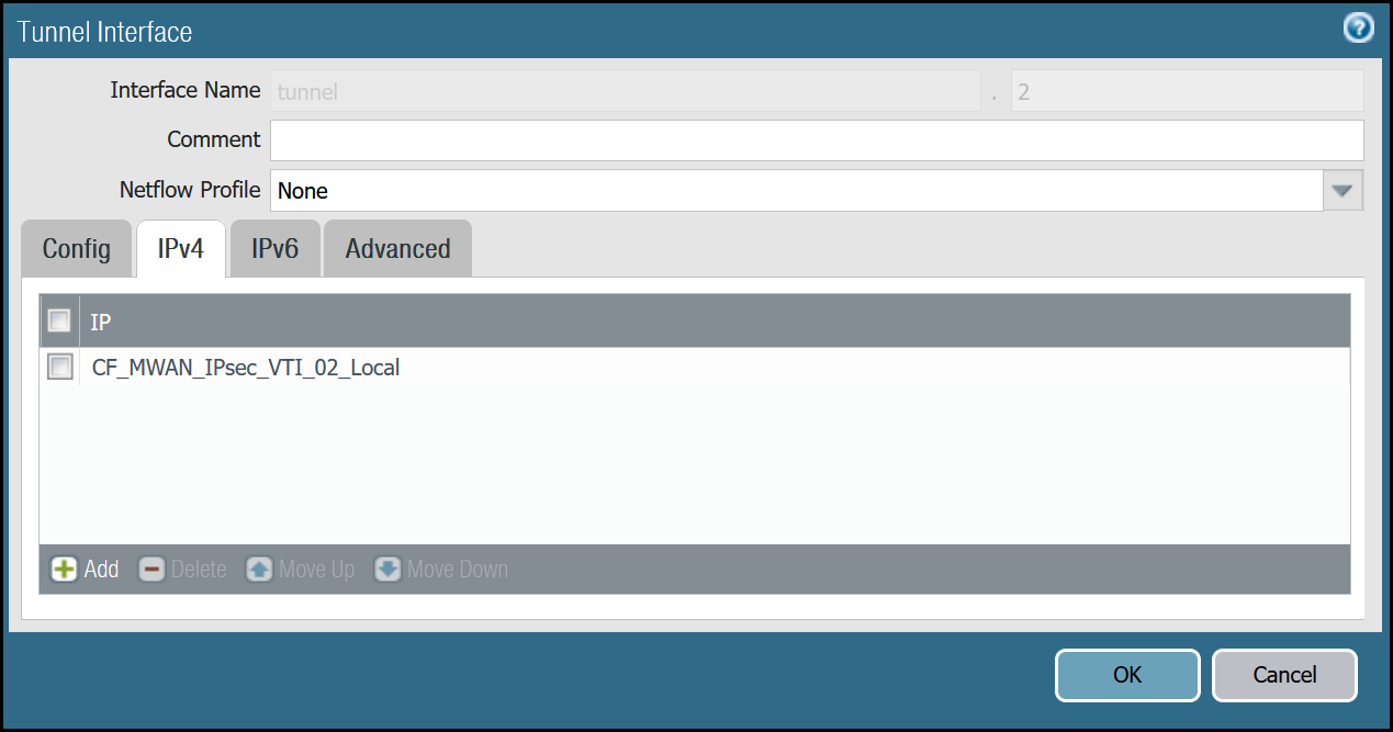
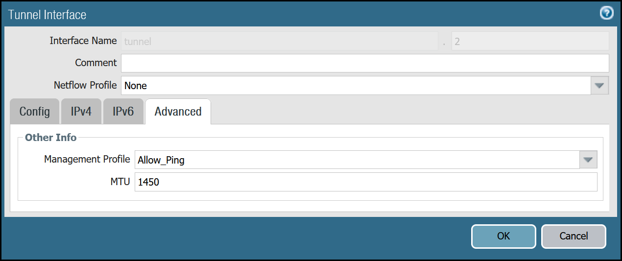
tunnel.2 - Cloudflare_L3_Zone
| Name | Option | Value |
|---|---|---|
| tunnel.2 | Netflow Profile | None |
| Config tab | Virtual Router | default |
| Security Zone | Cloudflare_L3_Zone | |
| IPv4 tab | IP | CF_MWAN_IPsec_VTI_02_Local address object |
| Advanced tab | Management Profile | Allow_Ping |
| MTU | 1450 |
After setting up your Tunnel interfaces, they should show up on the overview page:
Set up via command line
You can also set up your tunnels in the command line:
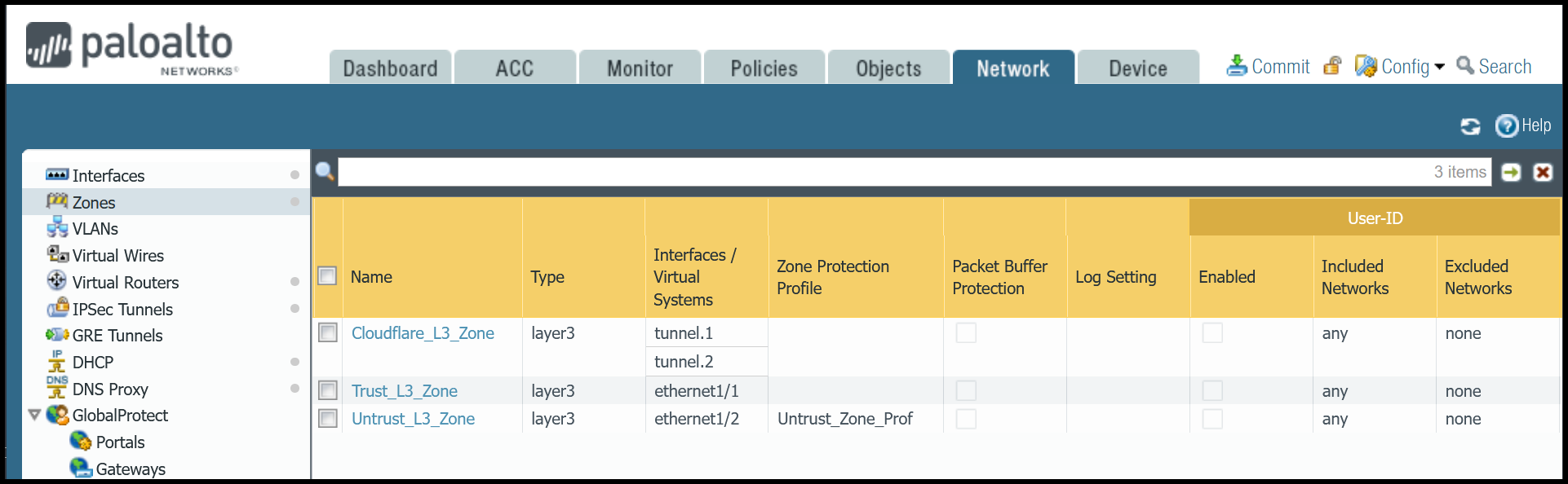
Zones
The Palo Alto Networks Next-Generation Firewall (NGFW) used to create this tutorial includes the following zones and corresponding network interfaces:
| Zone | Interface | Interface |
|---|---|---|
Trust_L3_Zone |
ethernet1/1 | |
Untrust_L3_Zone |
ethernet1/2 | |
Cloudflare_L3_Zone |
tunnel.1 | tunnel.2 |
The tunnel interfaces are placed in a separate zone to facilitate the configuration of more granular security policies. The use of any other zone for the tunnel interfaces will require adapting the configuration accordingly.
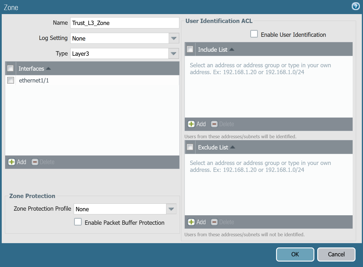
Set up via dashboard
Trust_L3_zone
| Name | Option | Value |
|---|---|---|
Trust_L3_zone |
Log setting | None |
| Type | Layer3 | |
| Interfaces | ethernet1/1 | |
| Zone Protection Profile | None |
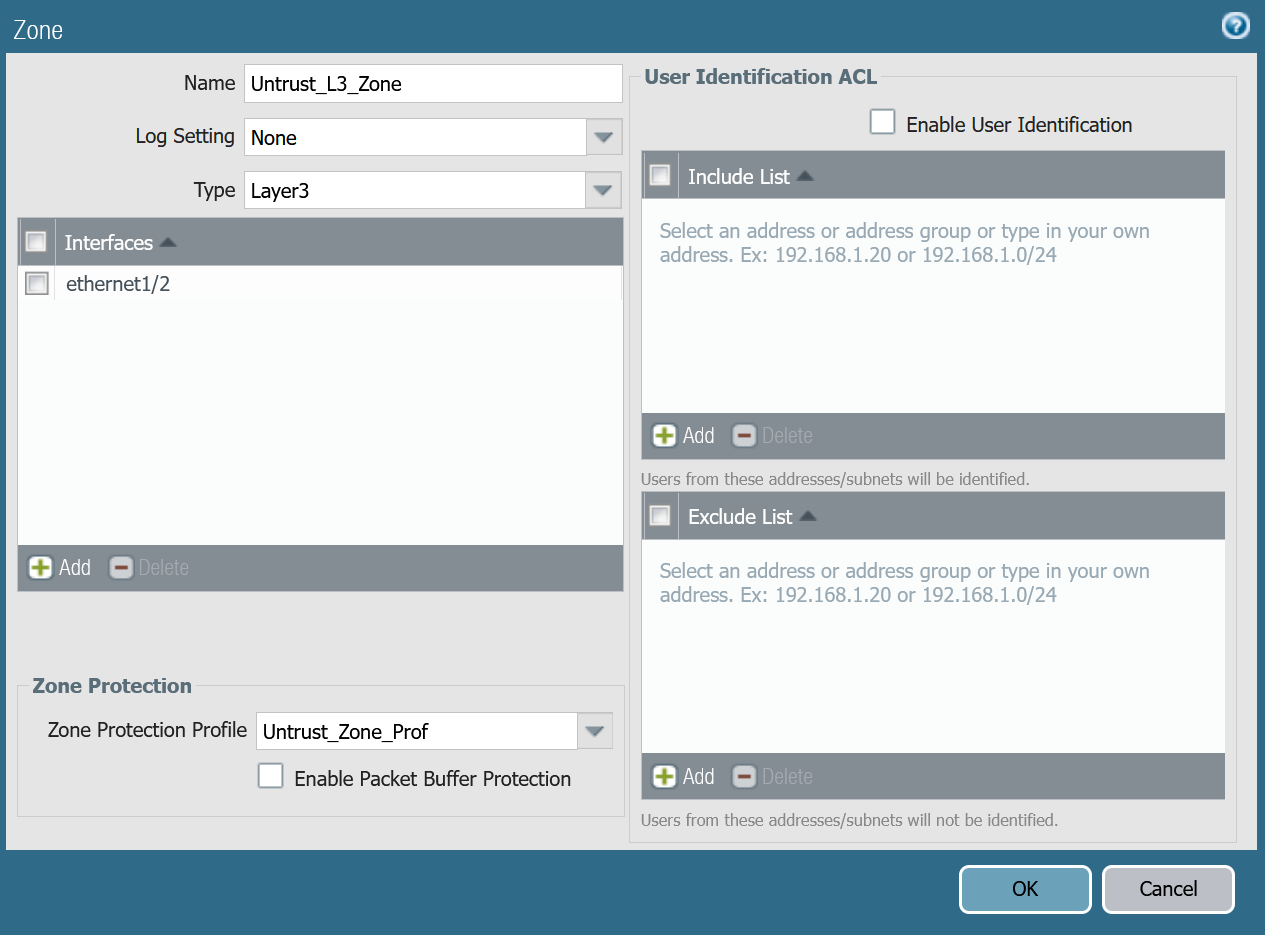
Untrust_L3_zone
| Name | Option | Value |
|---|---|---|
Untrust_L3_zone |
Log setting | None |
| Type | Layer3 | |
| Interfaces | ethernet1/2 | |
| Zone Protection Profile | Untrust_Zone_Prof |
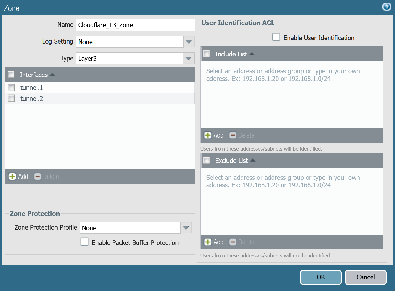
Cloudflare_L3_zone
| Name | Option | Value |
|---|---|---|
Cloudflare_L3_zone |
Log setting | None |
| Type | Layer3 | |
| Interfaces | tunnel.1 tunnel.2 |
|
| Zone Protection Profile | None |
Set up via command line
You can also use the command line to associate zones and interfaces:
Apply Changes
This would be a good time to save and commit the configuration changes made so far. Once complete, make sure you test basic connectivity to and from the firewall.
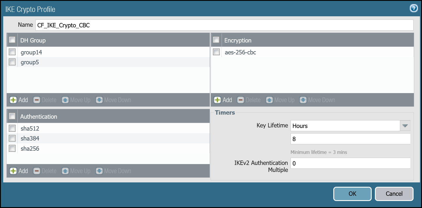
IKE crypto profile Phase 1
Add a new IKE crypto profile to support the required parameters for Phase 1.
Multiple DH groups and authentication settings are defined in the desired order. Palo Alto Networks Next-Generation Firewall (NGFW) will automatically negotiate the optimal settings based on specified values.
Set up via dashboard
| Name | Option | Value |
|---|---|---|
CF_IKE_Crypto_CBC |
DH Group | group14 |
| Authentication | sha512 sha384 sha256 |
|
| Encryption | aes-256-cbc | |
| Key Lifetime | 8 hours | |
| IKEv2 Authentication Multiple | 0 |
Set up via command line
You can also set up the crypto profile for Phase 1 via the command line:
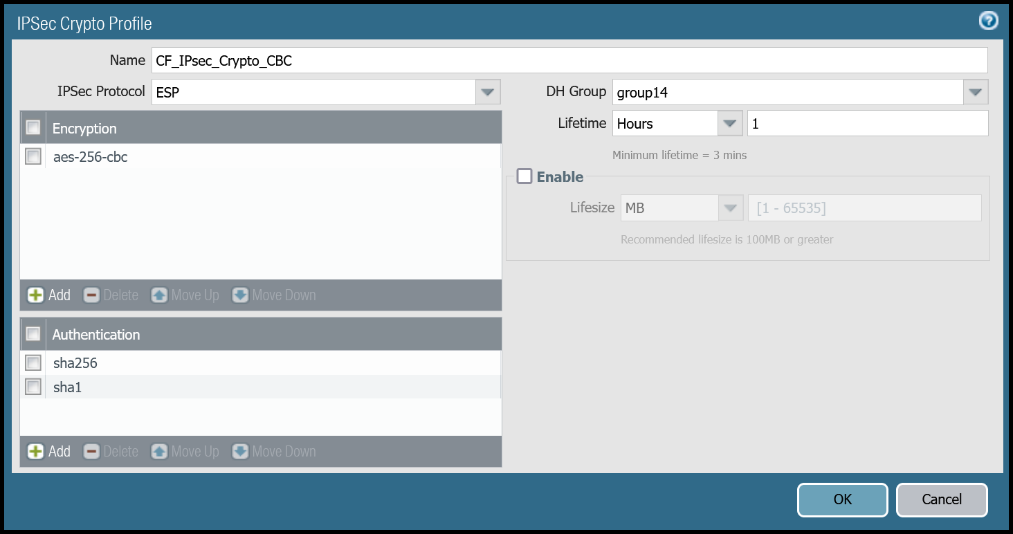
IPsec crypto profile Phase 2
Add a new IPsec crypto profile to support the required parameters for Phase 2.
Multiple Authentication settings are defined in the desired order. Palo Alto Networks Next-Generation Firewall (NGFW) will automatically negotiate the optimal settings based on specified values.
Set up via dashboard
| Name | Option | Value |
|---|---|---|
CF_IPsec_Crypto_CBC |
Encryption | aes-256-cbc |
| Authentication | sha256 sha1 |
|
| DH Group | group14 | |
| Lifetime | 1 hour |
Set up via command line
You can also set up the IPsec crypto profile for Phase 2 via the command line:
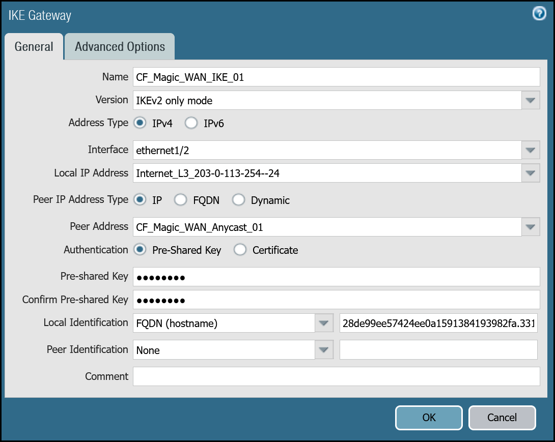
IKE Gateways
Define two IKE Gateways to establish the two IPsec tunnels to Cloudflare. Make sure to define the following values:
Set up via dashboard
Tunnel 1 settings: CF_Magic_WAN_IKE_01
| Tab | Option | Value |
|---|---|---|
| General tab | Name | CF_Magic_WAN_IKE_01 |
| Version | IKEv2 only mode. Make sure both IKE Gateways are based only on this setting. |
|
| Local IP Address | Internet_L3_203-0-113-254--24 |
|
| Peer address | CF_Magic_WAN_Anycast_01 |
|
| Pre-Shared Key | This value can be obtained from the Cloudflare dashboard - value is unique per tunnel. | |
| Local Identification | FQDN (hostname). You can obtain this value from the Cloudflare Dashboard - value is unique per tunnel. |
|
| Peer Identification | None | |
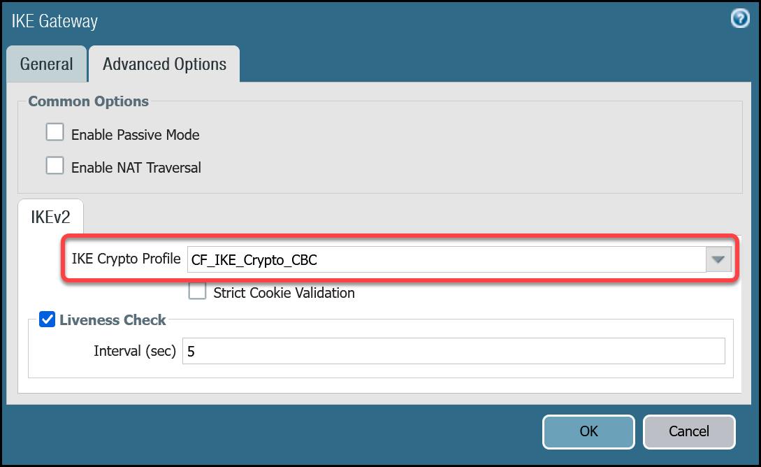
| Advanced tab | IKE Crypto Profile | CF_IKE_Crypto_CBC |
| Liveness Check | The default value (five seconds) is sufficient. This setting is used to periodically determine if there are any underlying connectivity issues that may adversely affect the creation of Phase 1 Security Associations. |
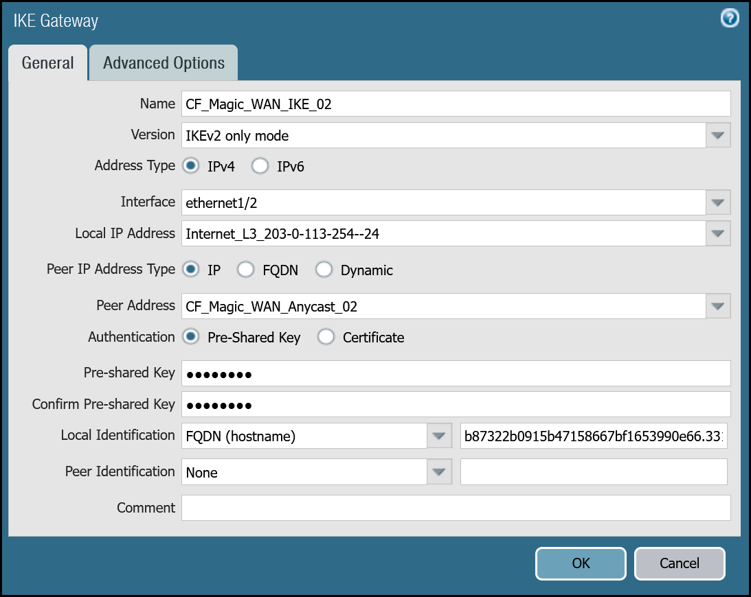
Tunnel 2 settings: CF_Magic_WAN_IKE_02
| Tab | Option | Value |
|---|---|---|
| General tab | Name | CF_Magic_WAN_IKE_02 |
| Version | IKEv2 only mode. Make sure both IKE Gateways are based only on this setting. |
|
| Local IP Address | Internet_L3_203-0-113-254--24 |
|
| Peer address | CF_Magic_WAN_Anycast_02 |
|
| Pre-Shared Key | This value can be obtained from the Cloudflare dashboard - value is unique per tunnel. | |
| Local Identification | FQDN (hostname). You can obtain this value from the Cloudflare Dashboard - value is unique per tunnel. |
|
| Peer Identification | None | |
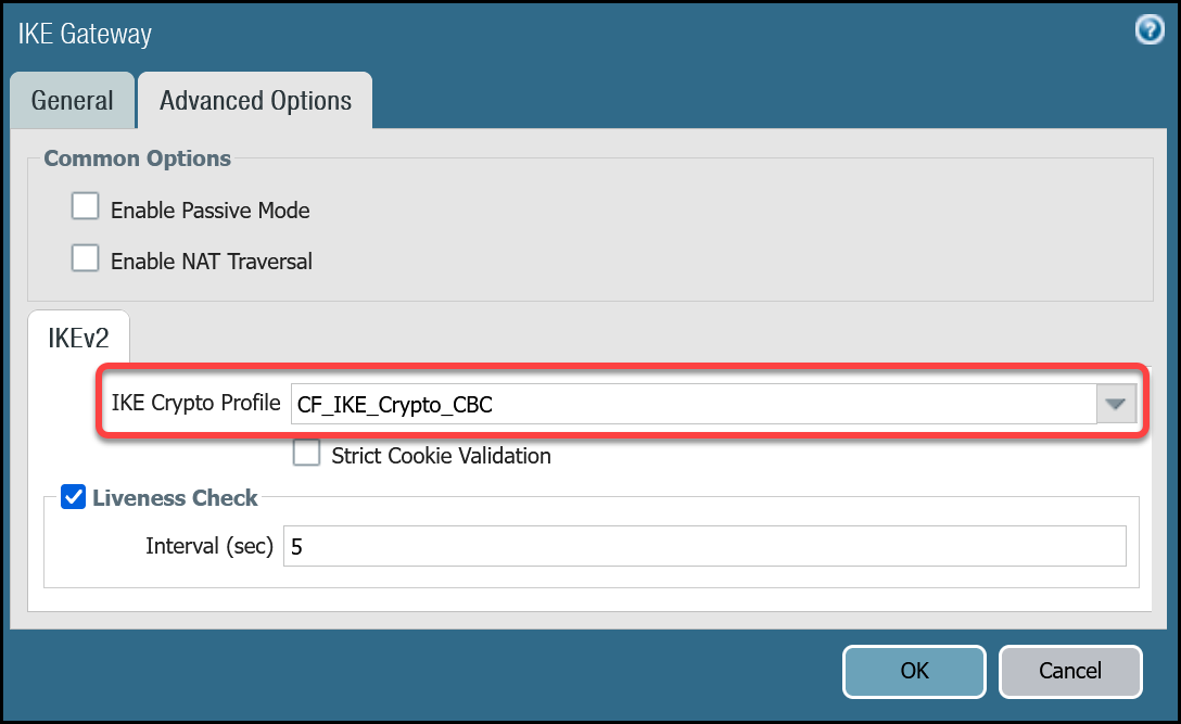
| Advanced tab | IKE crypto profile | CF_IKE_Crypto_CBC |
| Liveness Check | The default value (five seconds) is sufficient. This setting is used to periodically determine if there are any underlying connectivity issues that may adversely affect the creation of Phase 1 Security Associations. |
Set up via command line
Tunnel 1 settings: CF_Magic_WAN_IKE_01
Tunnel 2 settings: CF_Magic_WAN_IKE_02
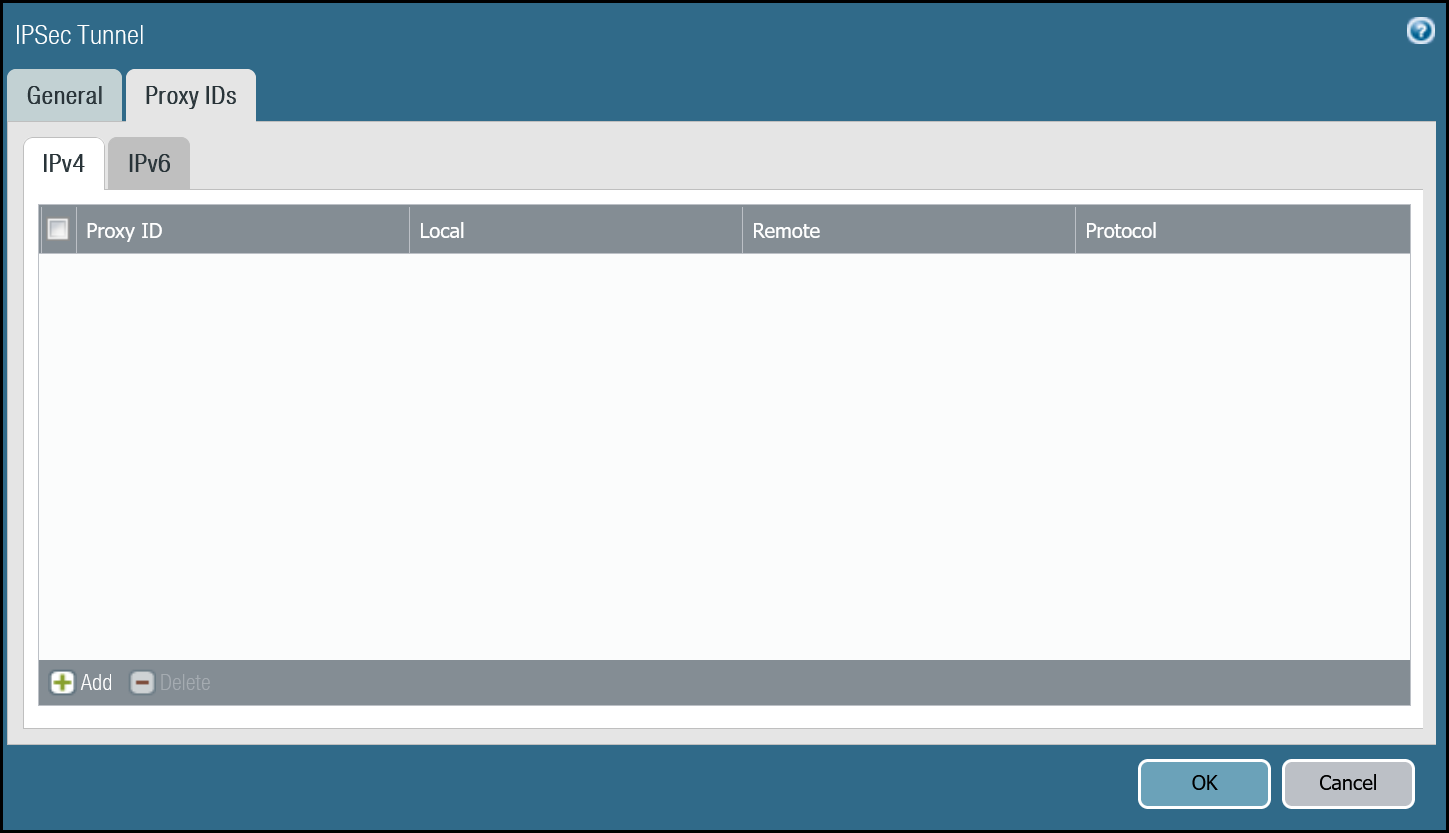
IPsec Tunnels
With the IKE Gateways defined, the next step is to configure two IPsec Tunnels - one corresponding to each of the two IKE Gateways configured in the previous section.
Prerequisites
There are a few prerequisites you should be aware of before continuing:
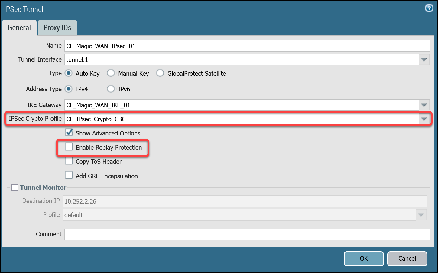
- Do not configure Proxy IDs. Magic WAN IPsec tunnels are based on the route-based VPN model. Proxy IDs are used with policy-based VPNs.
- Disable Replay Protection, under the Advanced Options.
- Disable Tunnel Monitor. It can cause undesirable results. Tunnel Monitor is a Palo Alto Networks proprietary feature that assumes there are Palo Alto Networks Next-Generation Firewall devices on both sides of the IPsec tunnel. Also, Tunnel Monitor is intended for use with IPsec tunnels based on IKEv1 (Magic WAN IPsec tunnels are based on IKEv2).
Set up via dashboard
Tunnel 1 settings: CF_Magic_WAN_IPsec_01
| Name | Option | Value |
|---|---|---|
CF_Magic_WAN_IPsec_01 |
Tunnel interface | tunnel.1 |
| IKE Gateway | CF_Magic_WAN_IKE_01 | |
| IPsec crypto profile | CF_IKE_Crypto_CBC | |
| Enable Replay Protection | Disable |
Tunnel 2 settings: CF_Magic_WAN_IPsec_02
| Name | Option | Value |
|---|---|---|
CF_Magic_WAN_IPsec_02 |
Tunnel interface | tunnel.2 |
| IKE Gateway | CF_Magic_WAN_IKE_02 | |
| IPsec crypto profile | CF_IKE_Crypto_CBC | |
| Enable Replay Protection | Disable |


Set up via command line
Tunnel 1 settings: CF_Magic_WAN_IPsec_01
Tunnel 2 settings: CF_Magic_WAN_IPsec_02
Apply Changes
This would be a good time to save and commit the configuration changes made thus far. Once complete, make sure you test basic connectivity across the IPsec tunnels.
IPsec tunnel connectivity tests
This is a good time to ensure the IPsec tunnels are established and to validate basic connectivity.
Verify IKE Phase 1 Communications
The first step is to verify IKE Phase 1 completed successfully:
Syntax
Example for CF_Magic_WAN_IKE_01
Example for CF_Magic_WAN_IKE_02
Troubleshooting IKE Phase 1 Communications
Magic WAN IPsec tunnels expect the customer device will initiate the IPsec tunnels. The tunnels may not establish if there is no traffic that would traverse the tunnel under normal conditions. In this case, it may be necessary to force IKE Phase 1.
Syntax
Example for CF_Magic_WAN_IKE_01
Example for CF_Magic_WAN_IKE_02
Repeat these commands for the respective tunnel to ensure the IKE SA(s) display as expected.
Verify IPsec Phase 2 Communications
To ensure the IPsec tunnels are established, ping the remote Virtual Tunnel Interface (Cloudflare side) from the command line on the Palo Alto Networks Next-Generation Firewall. Ensure you specify the source IP address of the ping from the local side of the Virtual Tunnel Interface:
Syntax
Example for CF_Magic_WAN_IPsec_01
Example for CF_Magic_WAN_IPsec_02
Troubleshooting IPsec Phase 2 Communications
Magic WAN IPsec tunnels expect the customer device will initiate the IPsec tunnels. The tunnels may not establish if there is no traffic that would traverse the tunnel under normal conditions. In this case, it may be necessary to force IPsec Phase 2. This is typically unnecessary as once IKE Phase 1 negotiates successfully, IPsec Phase 2 automatically establishes the tunnel. The test is still worth performing.
Syntax
Example for CF_Magic_WAN_IPsec_01
Example for CF_Magic_WAN_IPsec_02
Repeat these commands for the respective tunnel to ensure the IPsec SA(s) display as expected.
Ping Remote Virtual Tunnel interfaces
Use ping to source traffic from the IP address of the Virtual Tunnel interface on Palo Alto Networks Next-Generation Firewall (NGFW) to the IP address of the Virtual Tunnel Interface on the Cloudflare side of the IPsec tunnel.
Syntax
Example for Tunnel 1
Example for Tunnel 2
Virtual Router
While we will leverage policy-based forwarding to implement policy-based routing, it is still a good idea to configure routing on the Virtual Router.
Cloudflare Magic WAN implements equal-cost multi-path (ECMP) routing to steer traffic across IPsec tunnels. The default behavior is to load balance traffic equally across both tunnels.
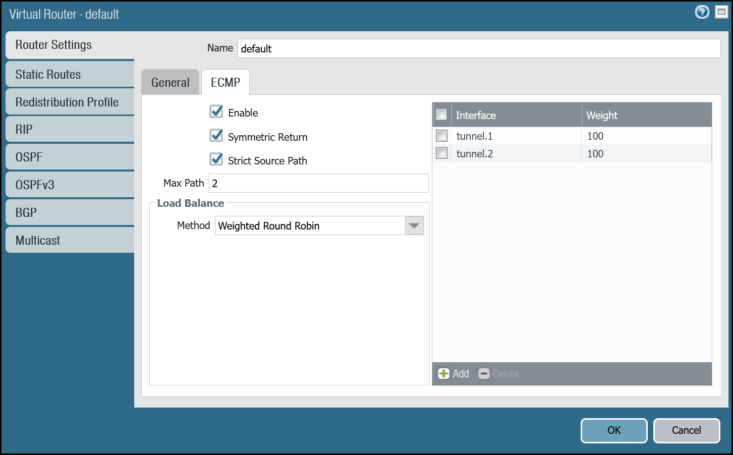
Enable ECMP
First, ensure the General tab displays both the Ethernet and tunnel interfaces. If any of the interfaces are not displayed, either use Add to specify the missing interface(s), or visit the Interfaces menu to ensure the relevant Virtual Router is selected.
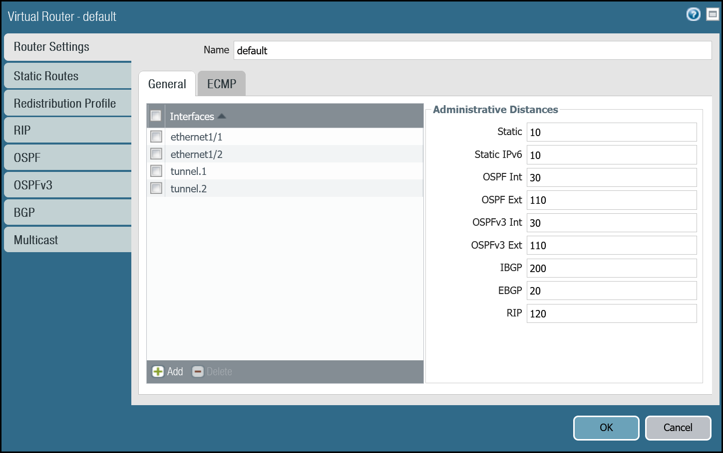
- Open the Router settings for the default Virtual Router and select the ECMP tab.
- Select the checkboxes next to Enable, Symmetric Return, and Strict Source Path (all three checkboxes should be selected).
- Under Load Balance, change the Method from IP Modulo to Weighted Round Robin and add both tunnel interfaces. Ensure the weights match the weights defined in Magic WAN Static Routes (reference the Cloudflare Dashboard).
You can also use the command line to make these changes:
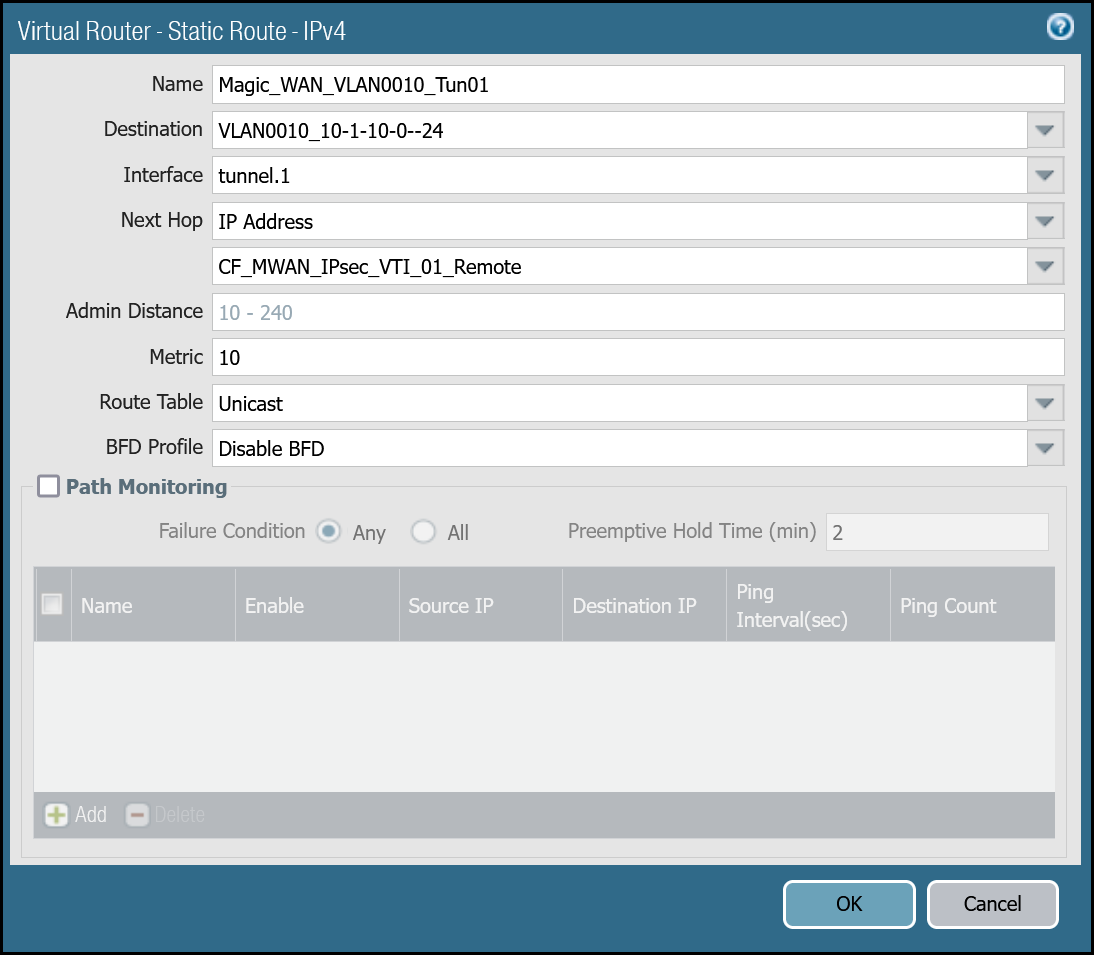
Add static routes
Add two static routes for each Magic WAN Protected Network - one for each of the two tunnel interfaces.
The environment used for this tutorial assumes two Magic WAN Protected Networks:
- VLAN0010:
10.1.10.0/24 - VLAN0020:
10.1.20.0/24
VLAN0010 (10.1.10.0/24) via tunnel.1
| Name | Option | Value |
|---|---|---|
Magic_WAN_VLAN0010_Tun01 |
Destination | VLAN0010_10-1-10-0–24 |
| Interface | tunnel.1 | |
| Next hop | IP Address | |
| CF_MWAN_IPsec_VTI_01_Remote | ||
| Metric | 10 |
|
| Route Table | Unicast | |
| BFD Profile | Disable BFD |
VLAN0010 (10.1.10.0/24) via tunnel.2
| Name | Option | Value |
|---|---|---|
Magic_WAN_VLAN0010_Tun02 |
Destination | VLAN0010_10-1-10-0–24 |
| Interface | tunnel.2 | |
| Next hop | IP Address | |
| CF_MWAN_IPsec_VTI_02_Remote | ||
| Metric | 11 |
|
| Route Table | Unicast | |
| BFD Profile | Disable BFD |

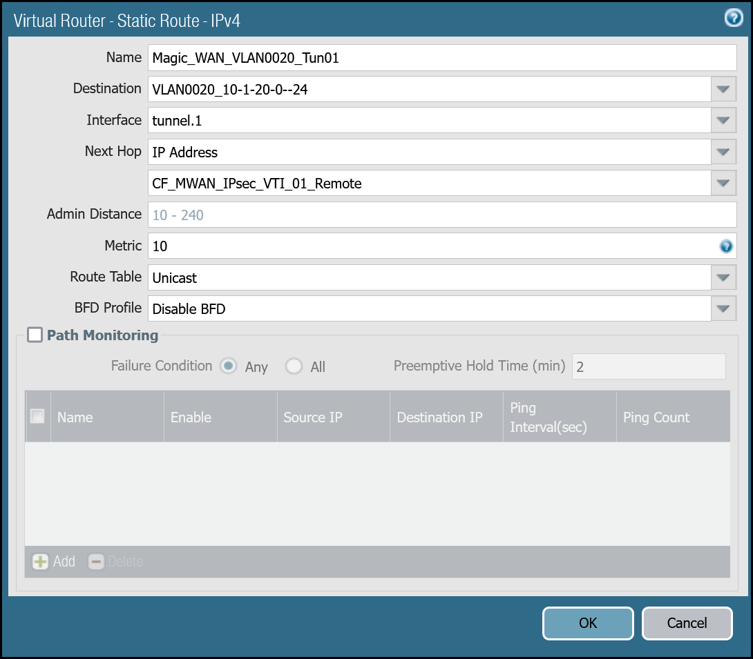
VLAN0020 (10.1.20.0/24) via tunnel.1
| Name | Option | Value |
|---|---|---|
Magic_WAN_VLAN0020_Tun01 |
Destination | VLAN0020_10-1-20-0–24 |
| Interface | tunnel.1 | |
| Next hop | IP Address | |
| CF_MWAN_IPsec_VTI_01_Remote | ||
| Metric | 10 |
|
| Route Table | Unicast | |
| BFD Profile | Disable BFD |
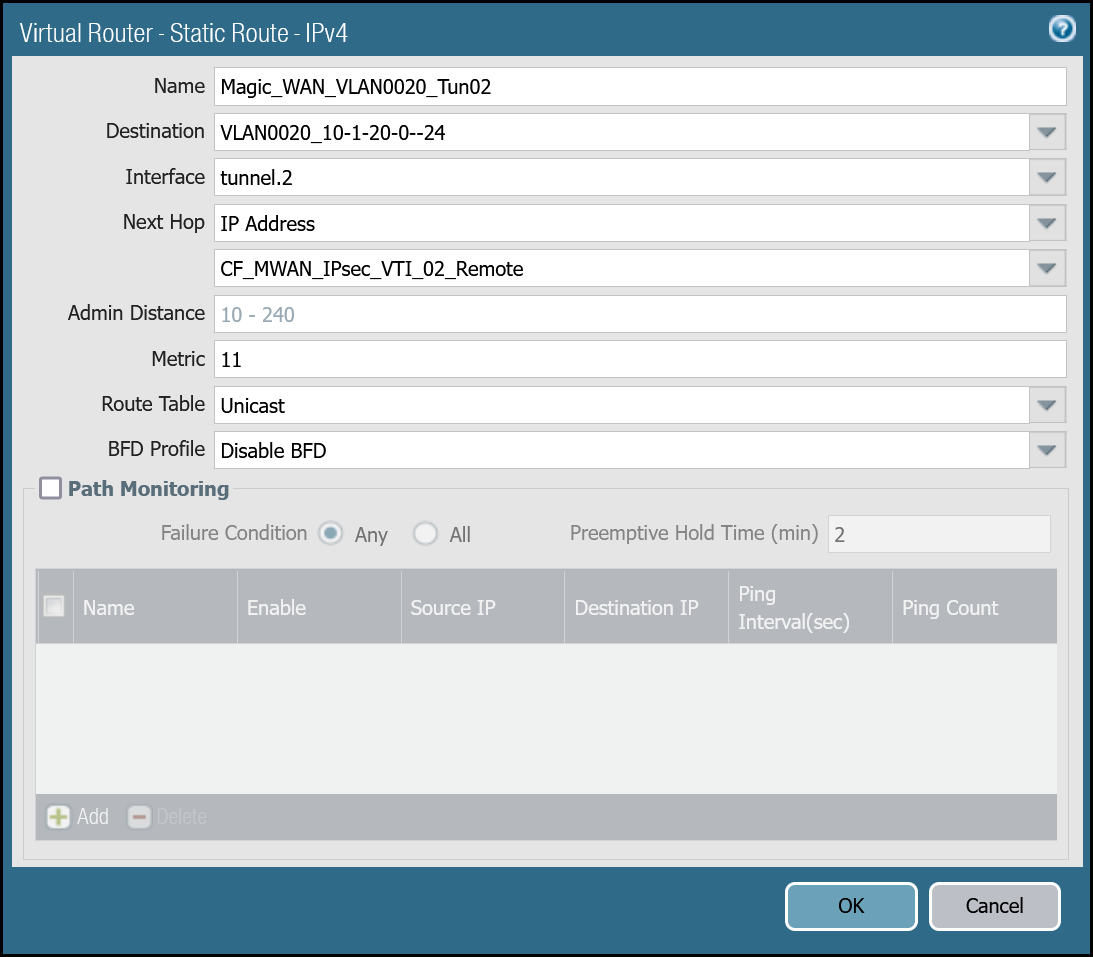
VLAN0020 (10.1.20.0/24) via tunnel.2
| Name | Option | Value |
|---|---|---|
Magic_WAN_VLAN0020_Tun02 |
Destination | VLAN0020_10-1-20-0–24 |
| Interface | tunnel.2 | |
| Next hop | IP Address | |
| CF_MWAN_IPsec_VTI_02_Remote | ||
| Metric | 11 |
|
| Route Table | Unicast | |
| BFD Profile | Disable BFD |
You can also configure these settings via command line:
VLAN0010 - 10.1.10.0/24
VLAN0020 - 10.1.20.0/24
Magic health checks
Cloudflare crafts ICMP probes which are sent through the IPsec tunnels from random servers across Cloudflare’s global Anycast network. These ICMP probes are unique because an ICMP reply packet is sent (as opposed to an ICMP Request).
Cloudflare Magic WAN customers must configure IPsec tunnels to use custom Anycast IP addresses for the health check endpoints:
- CF_Health_Check_Anycast_01:
172.64.240.253 - CF_Health_Check_Anycast_02:
172.64.240.254
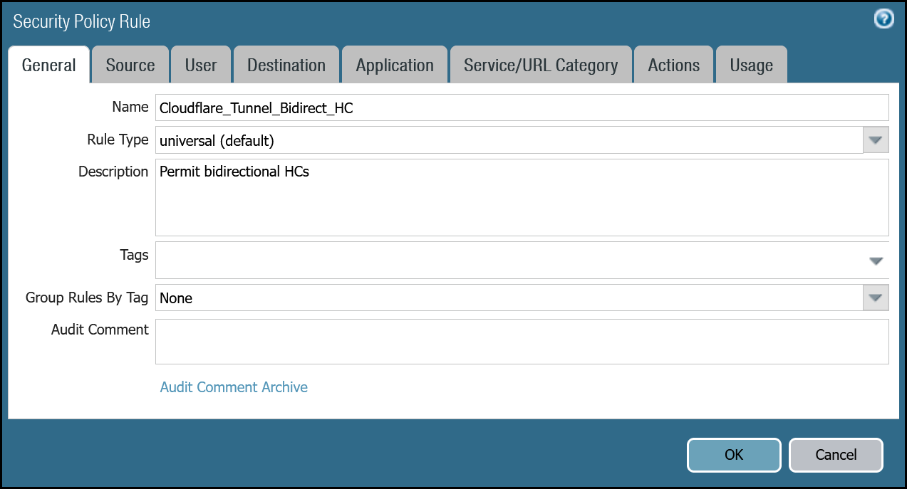
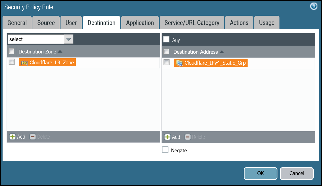
Security Policy - Tunnel health checks
You must define a rule to allow the ICMP reply probes as Palo Alto Networks Next-Generation Firewall’s default behavior will drop the health checks.
Setup via dashboard
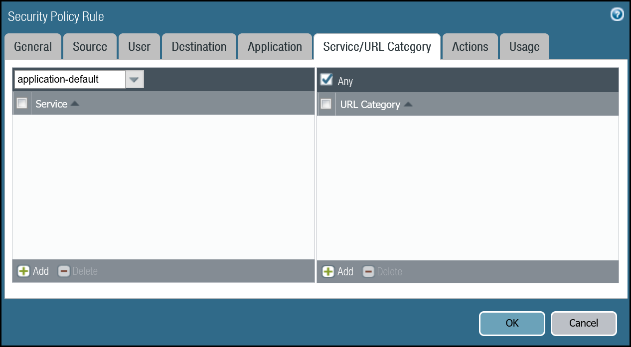
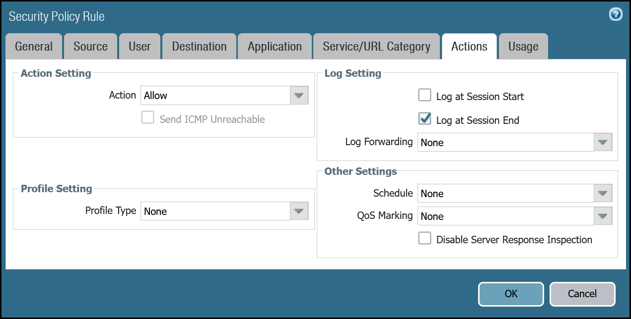
| Name | Option | Value |
|---|---|---|
Cloudflare_Tunnel_Bidirect_HC |
Rule Type | universal (default) |
| Description | Permit bidirectional HCs |
|
| Group Rules By Tag | None | |
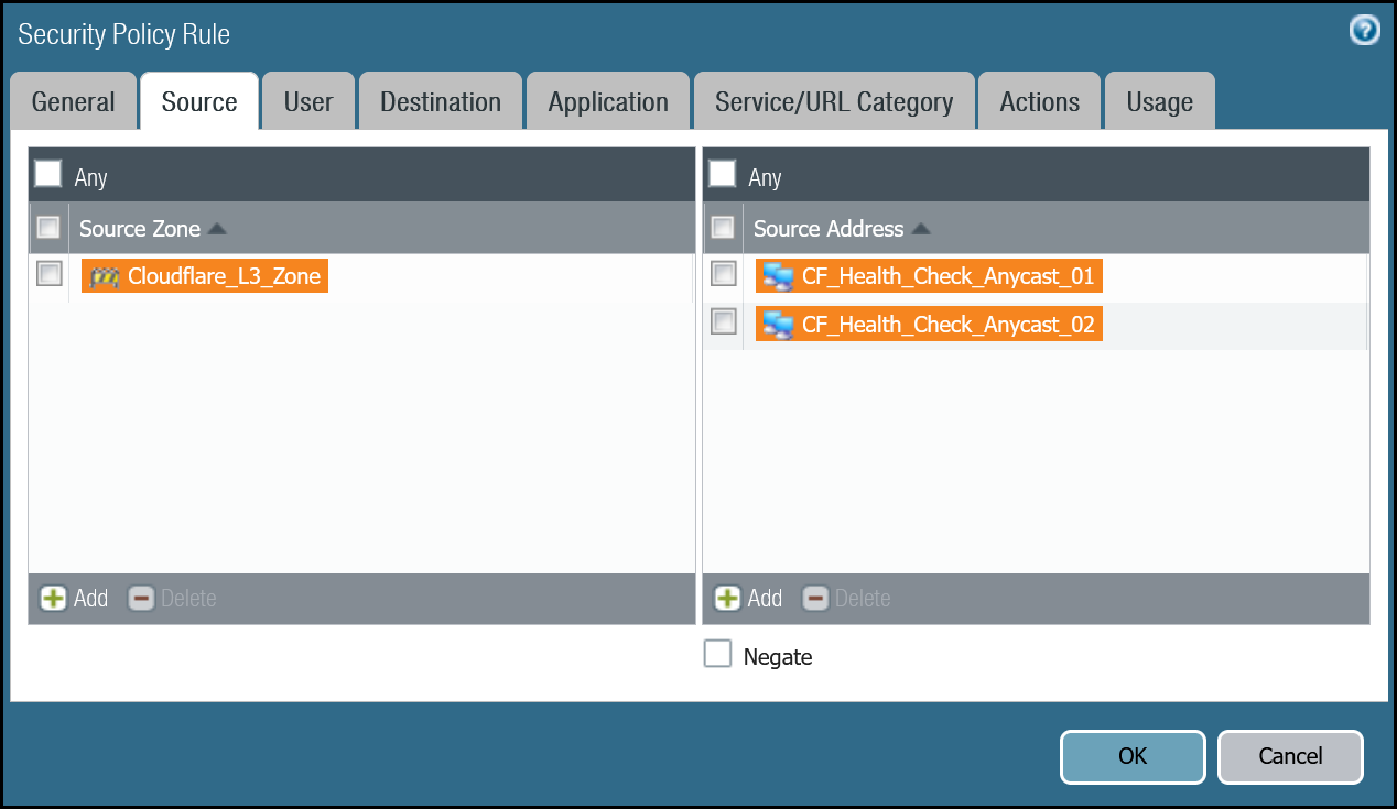
| Source tab | Source Zone | Cloudflare_L3_Zone |
| Source Address | CF_Health_Check_Anycast_01 CF_Health_Check_Anycast_02 |
|
| Destination tab | Destination Zone | Cloudflare_L3_Zone |
| Destination Address | Cloudflare_IPv4_Static_Grp | |
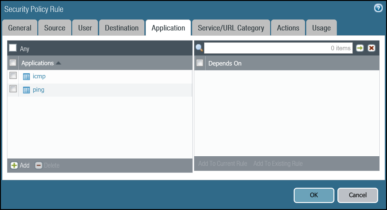
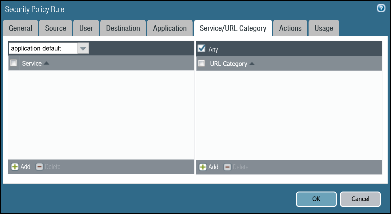
| Application tab | Applications | icmp ping |
| Actions tab | Action | Allow |
| Log Setting | Log at Session End | |
| Profile type | None | |
| Schedule | None | |
| QoS Marking | None |

Setup via command line
Policy-based forwarding - tunnel health checks
Traffic matching the Security Rule defined in the last step must be routed symmetrically across the tunnel the ingress traffic was received through. Two policy-based forwarding rules ensure the traffic is routed accordingly.
Ensure have the following:
- Source Zone:
Cloudflare_L3_Zone - Source Addresses:
CF_Health_Check_Anycast_01andCF_Health_Check_Anycast_02 - Destination Zone:
Cloudflare_L3_Zone - Destination Addresses:
Cloudflare_IPv4_Static_Grp - Application:
icmpandping
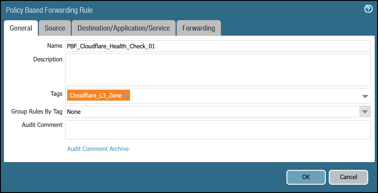
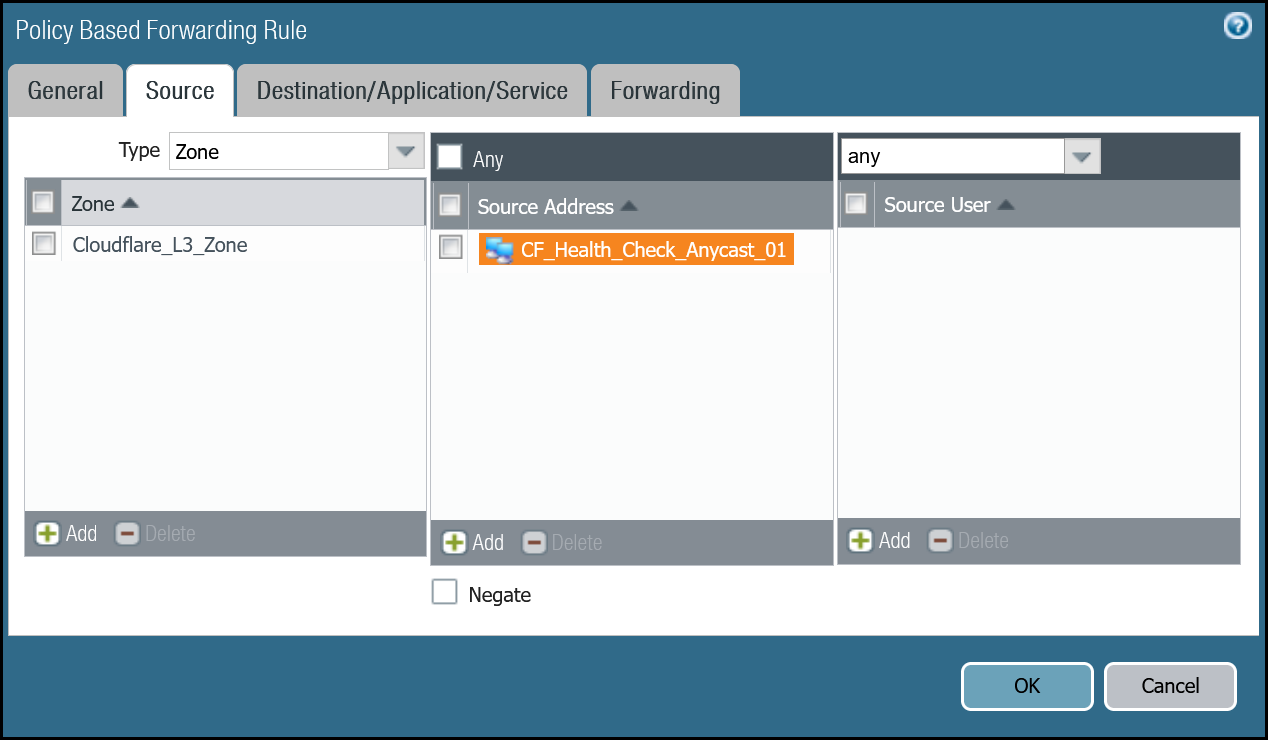
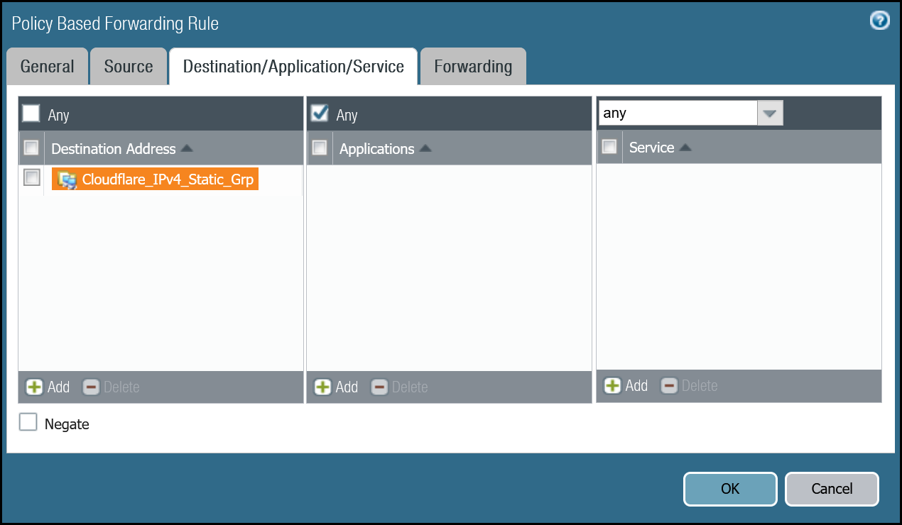
Set up via dashboard tunnel.1
| Name | Option | Value |
|---|---|---|
PBF_Cloudflare_Health_Check_01 |
Tags | Cloudflare_L3_Zone |
| Group Rules By Tag | None | |
| Source tab | Type | Zone |
| Zone | Cloudflare_L3_Zone | |
| Source Address | CF_Health_Check_Anycast_01 | |
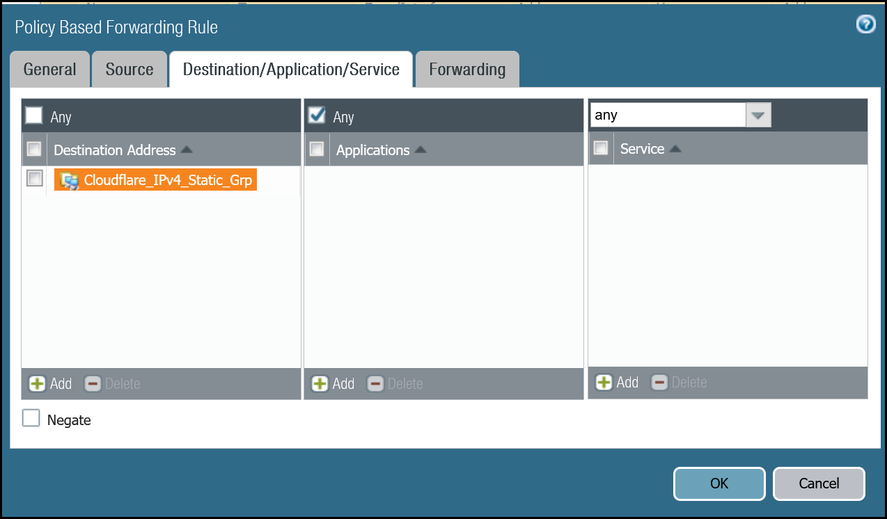
| Destination/Application/Service tab | Destination Address | Cloudflare_IPv4_Static_Grp |
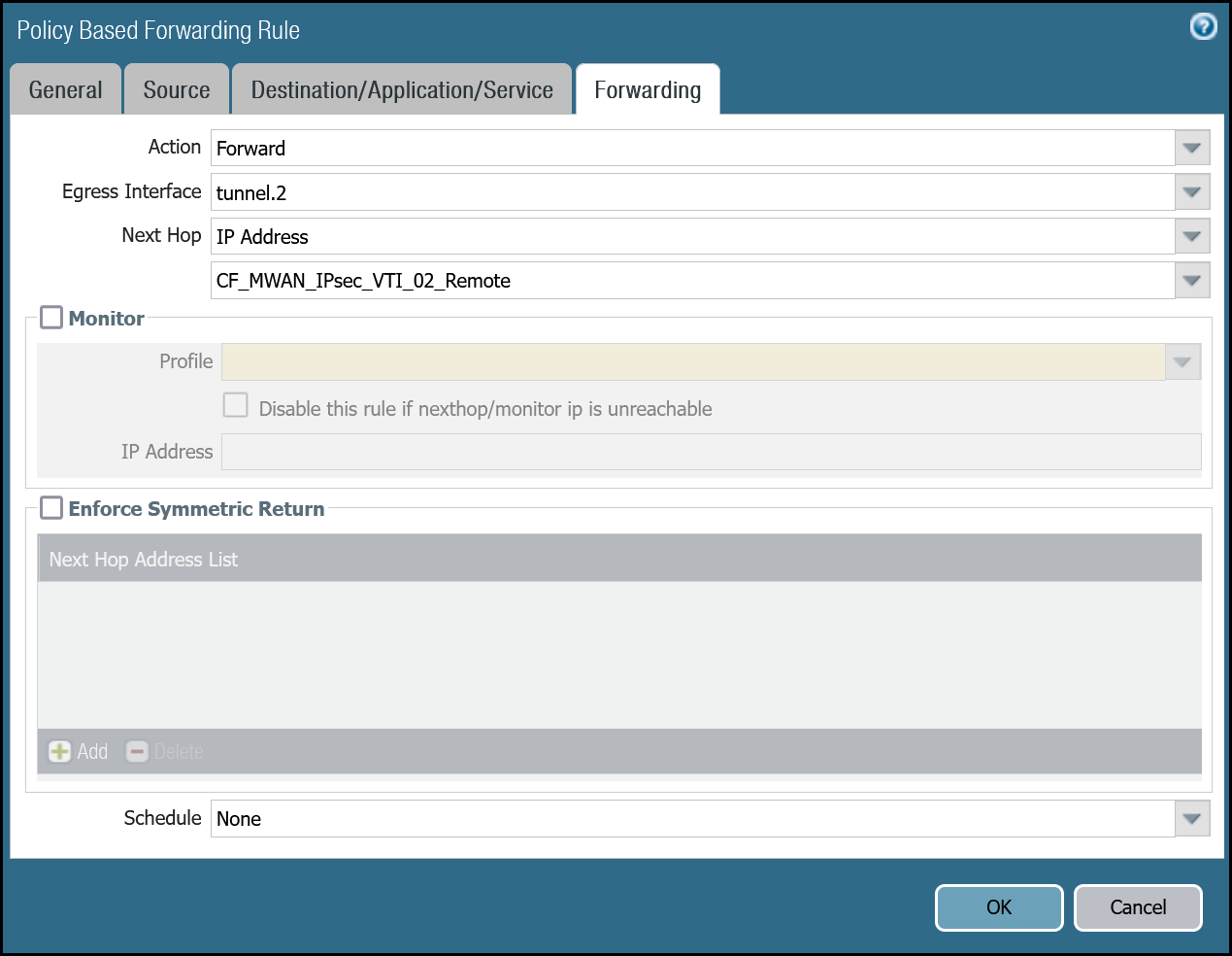
| Forwarding tab | Action | Forward |
| Egress interface | tunnel.1 | |
| Next Hop | IP Address | |
| CF_MWAN_IPsec_VTI_01_Remote |

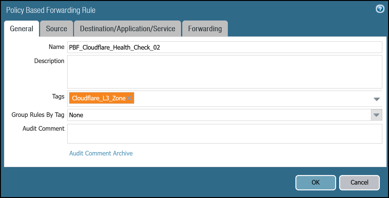
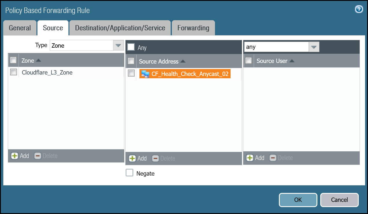
Set up via dashboard tunnel.2
| Name | Option | Value |
|---|---|---|
PBF_Cloudflare_Health_Check_02 |
Tags | Cloudflare_L3_Zone |
| Group Rules By Tag | None | |
| Source tab | Type | Zone |
| Zone | Cloudflare_L3_Zone | |
| Source Address | CF_Health_Check_Anycast_02 | |
| Destination/Application/service tab | Destination Address | Cloudflare_IPv4_Static_Grp |
| Forwarding tab | Action | Forward |
| Egress interface | tunnel.2 | |
| Next Hop | IP Address | |
| CF_MWAN_IPsec_VTI_02_Remote |
Set up via command line tunnel.1
Set up via command line tunnel.2
Troubleshooting tunnel health checks
Security Policy
Use the Traffic log viewer to ensure that the health check traffic is allowed. Start by adding a rule to filter the logs based on the name of the Security Policy rule permitting the applicable traffic.
Filter by rule name
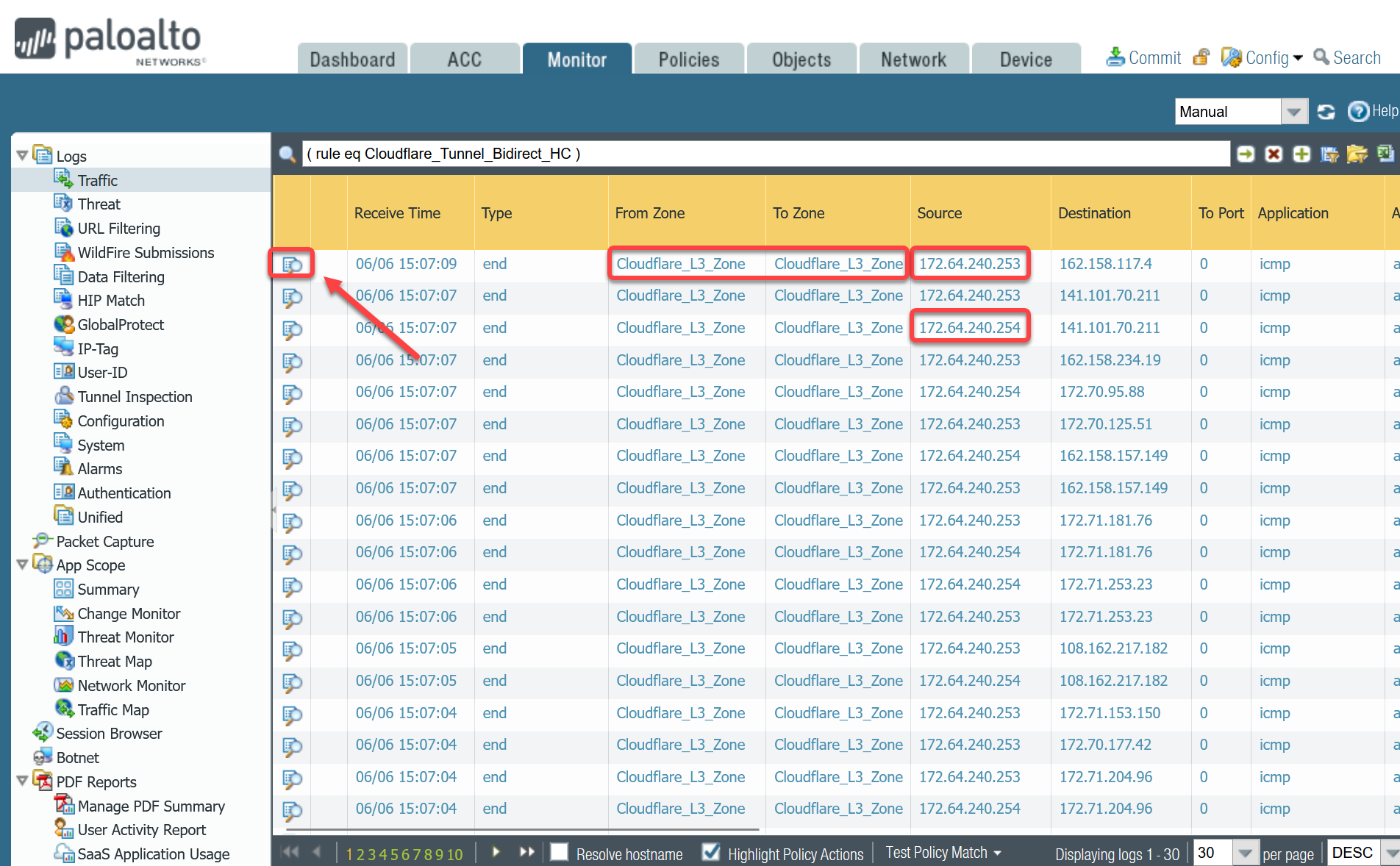
If you do not see any traffic matching the filter, replace the filter with one that displays log entries based on the addresses associated with the CF_Health_Check_Anycast_01 and CF_Health_Check_Anycast_02 Address objects.
Filter by health check Anycast IPs
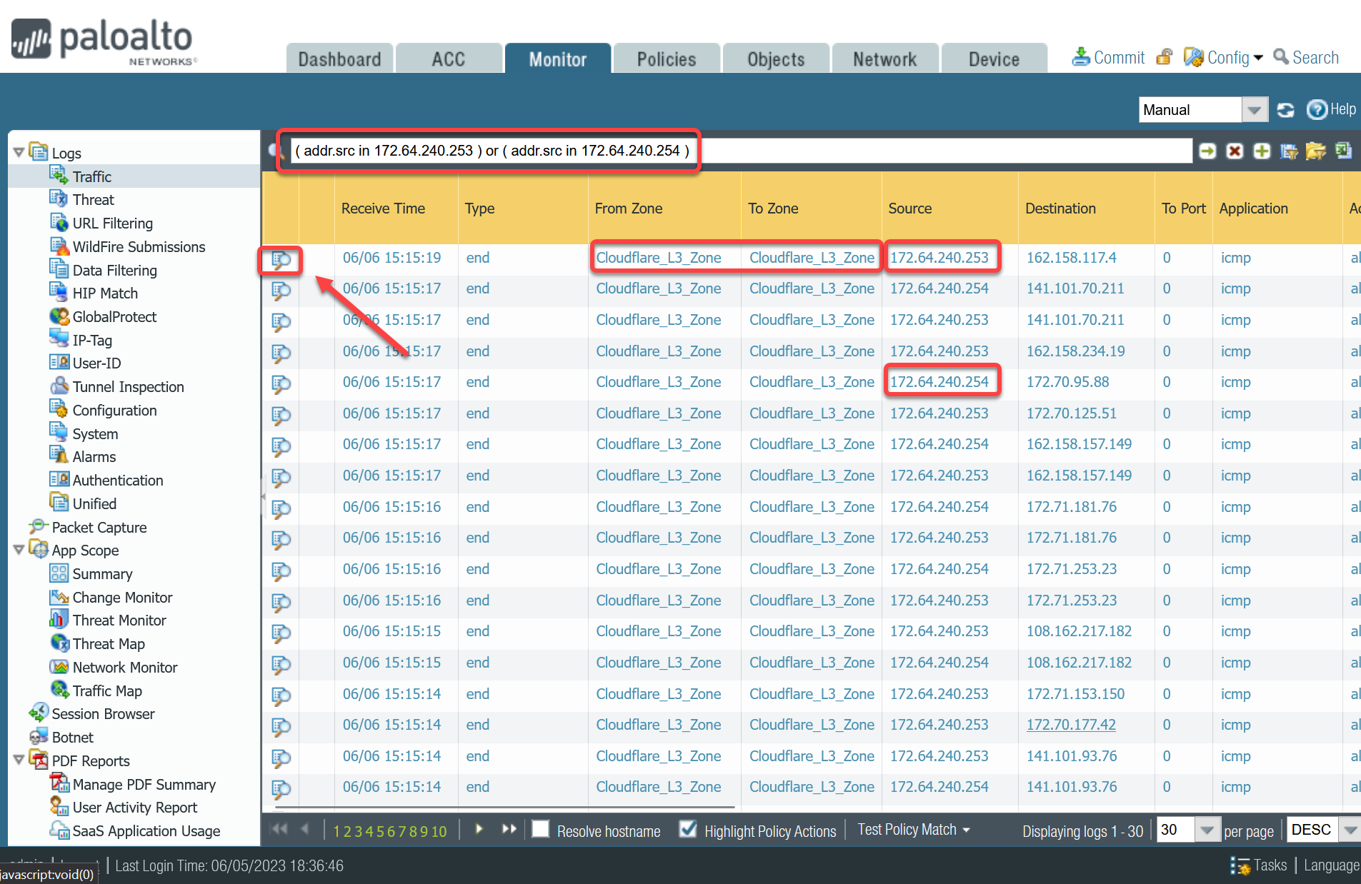
Policy-based forwarding
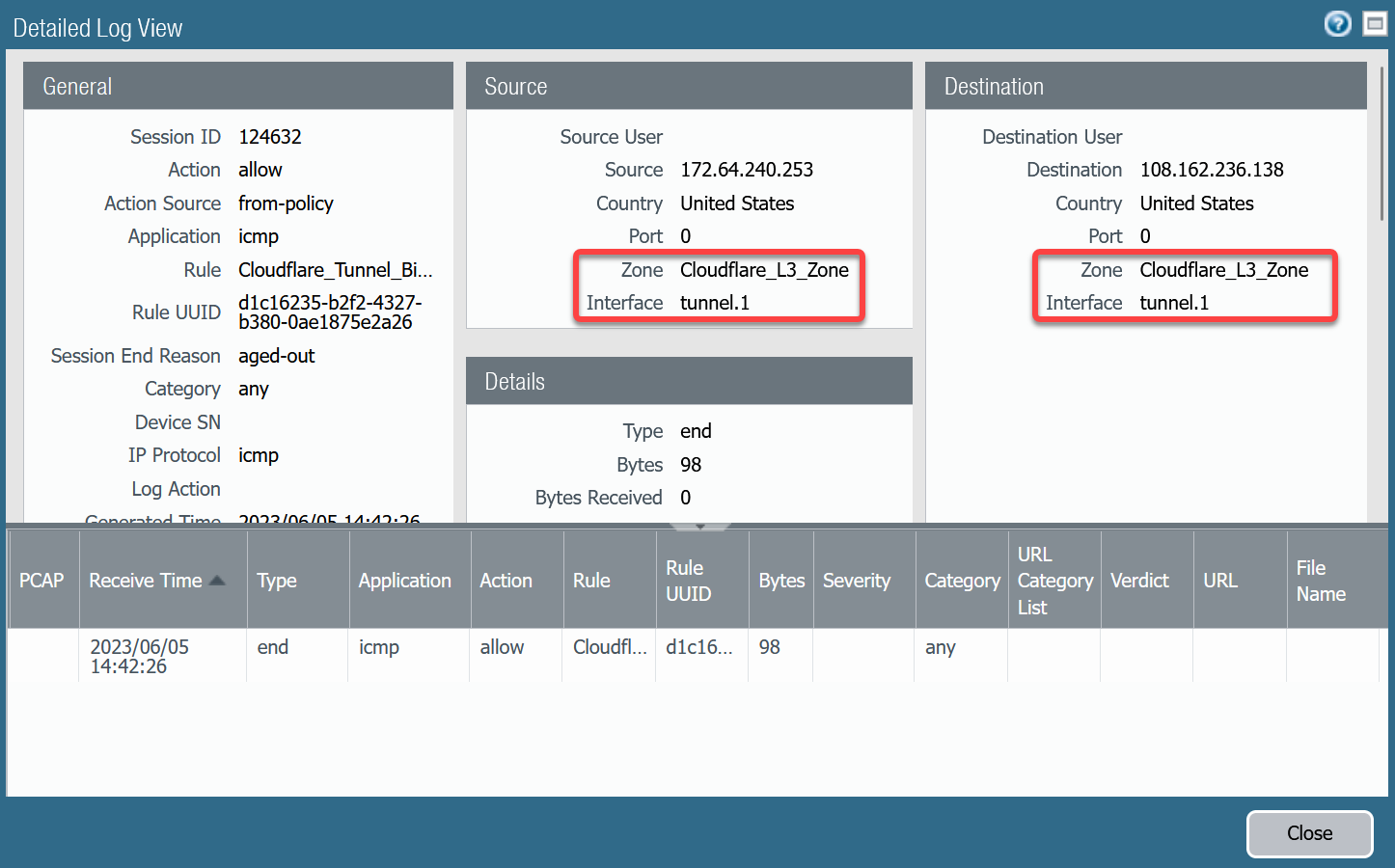
Troubleshooting policy-based forwarding can be a bit challenging. The ideal way to determine if traffic is flowing through the intended path is to select the detailed view for a log entry.
-
Select the magnifying glass next to one of the log entries with source IP address
172.64.240.253. -
Traffic originating from
CF_Health_Check_Anycast_01(172.64.240.253) should ingress and egress interface tunnel.1.
-
Select the magnifying glass next to one of the log entries with source IP address
172.64.240.254. -
Traffic originating from
CF_Health_Check_Anycast_02(172.64.240.254) should ingress and egress interface tunnel.2.
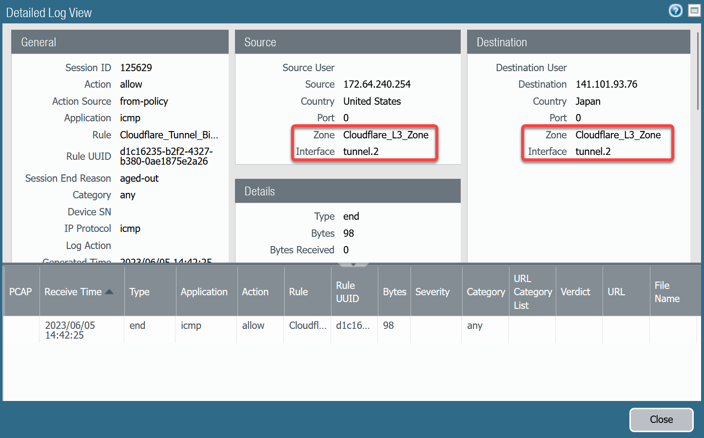
If the traffic is not ingressing/egressing the same interface, you likely have an issue with the policy-based forwarding rule(s) not matching.
Security Policies - Production Traffic
As mentioned earlier, this tutorial includes examples for two different use-cases:
- Magic WAN: permit traffic between two or more locations with RFC-1918 private non-routable address space.
- Magic WAN with Cloudflare Zero Trust (Gateway egress): same as Magic WAN with the addition of outbound Internet access from Magic WAN protected sites egressing the Cloudflare edge network.
Magic WAN only
Rules must be defined to facilitate traffic from the trust network to the Magic WAN protected sites. While it may be possible to define one rule for traffic in both directions, this example includes two rules:
-
From Trust to Magic WAN protected sites.
-
From Magic WAN protected sites to Trust.
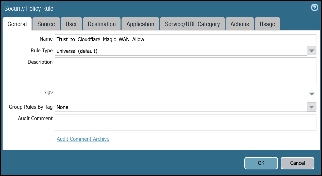
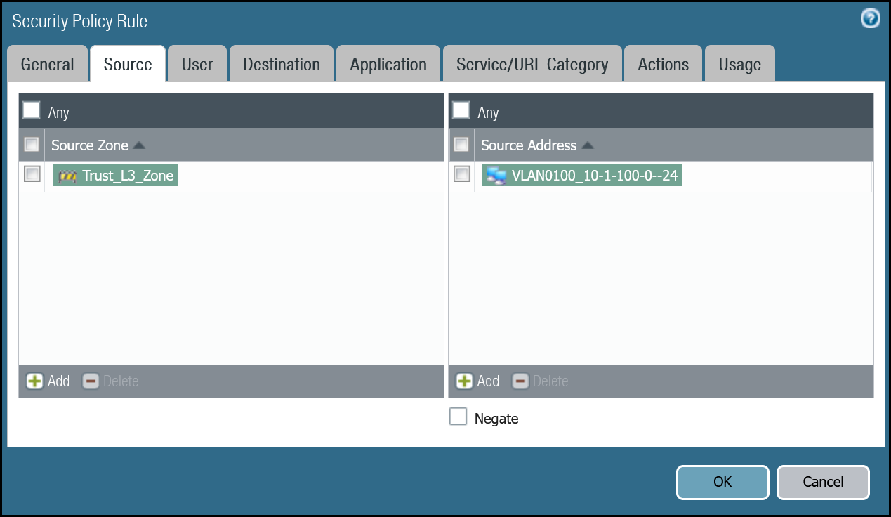
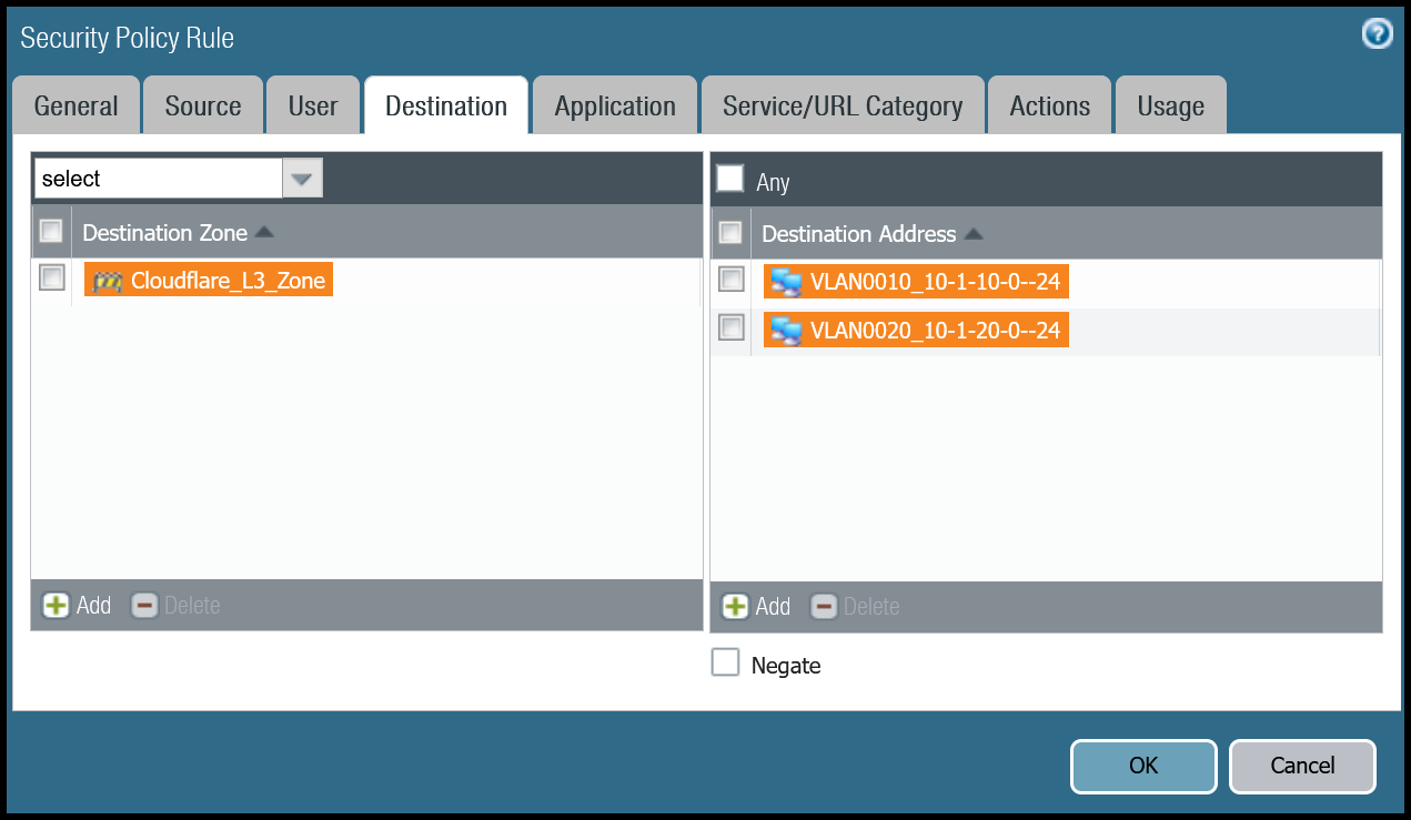
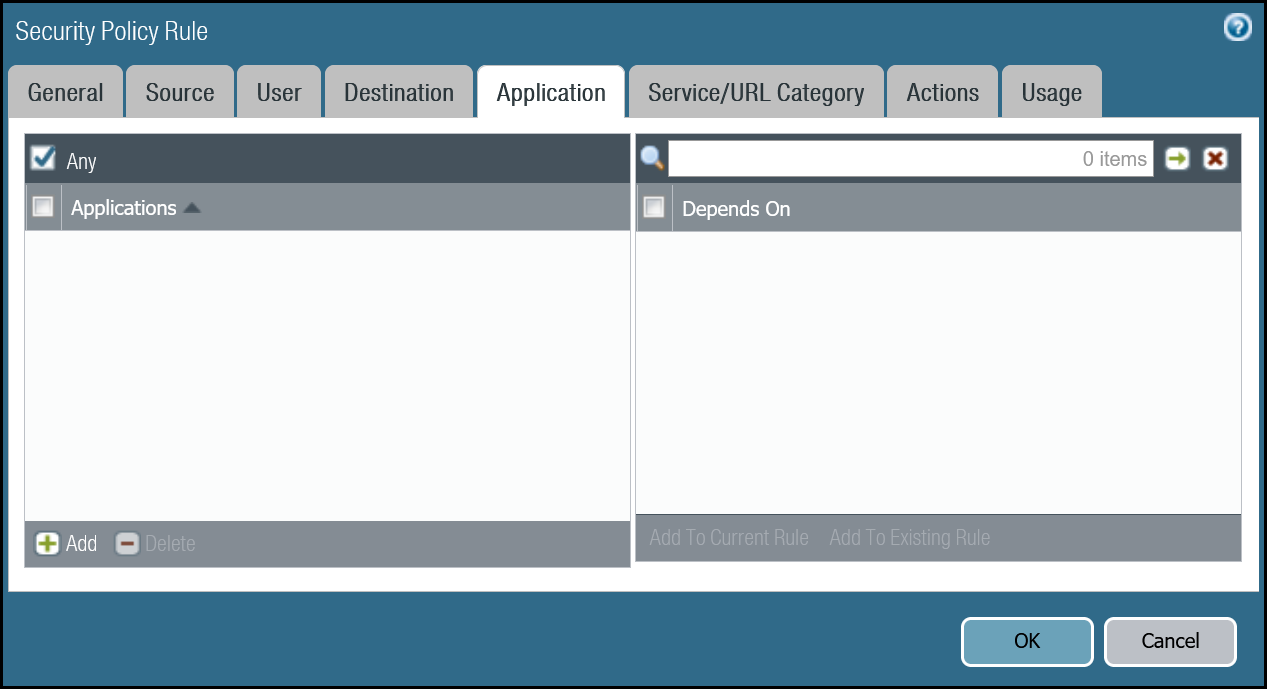
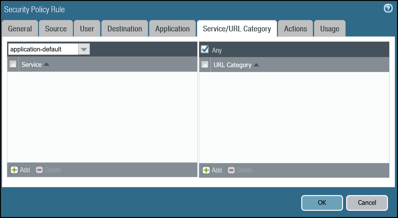
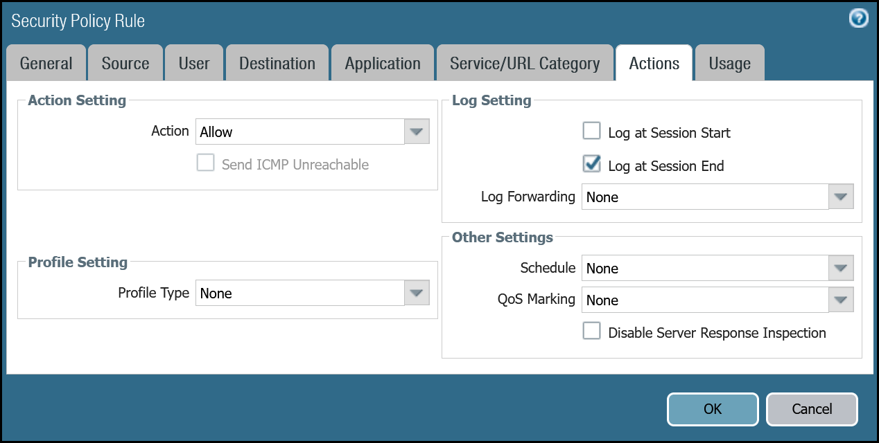
Trust to Magic WAN dashboard
| Name | Option | Value |
|---|---|---|
Trust_to_Cloudflare_Magic_WAN_Allow |
Rule Type | universal (default) |
| Group Rules by Tag | None | |
| Source tab | Source Zone | Trust_L3_Zone |
| Source Address | VLAN0100_10-1-100-0–24 | |
| Destination tab | Destination Zone | Cloudflare_L3_Zone |
| Destination Address | VLAN0010_10-1-10-0–24 VLAN0020_10-1-20-0–24 |
|
| Actions tab | Action | Allow |
| Log Setting | Log at Session End | |
| Profile type | None | |
| Schedule | None | |
| QoS Marking | None |
Trust to Magic WAN command line
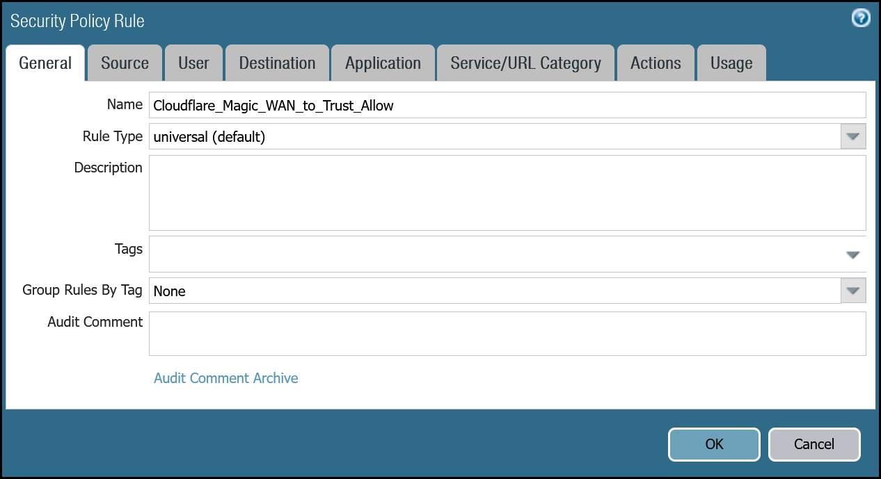
Magic WAN to Trust dashboard
| Name | Option | Value |
|---|---|---|
Cloudflare_Magic_WAN_to_Trust_Allow |
Rule Type | universal (default) |
| Group Rules by Tag | None | |
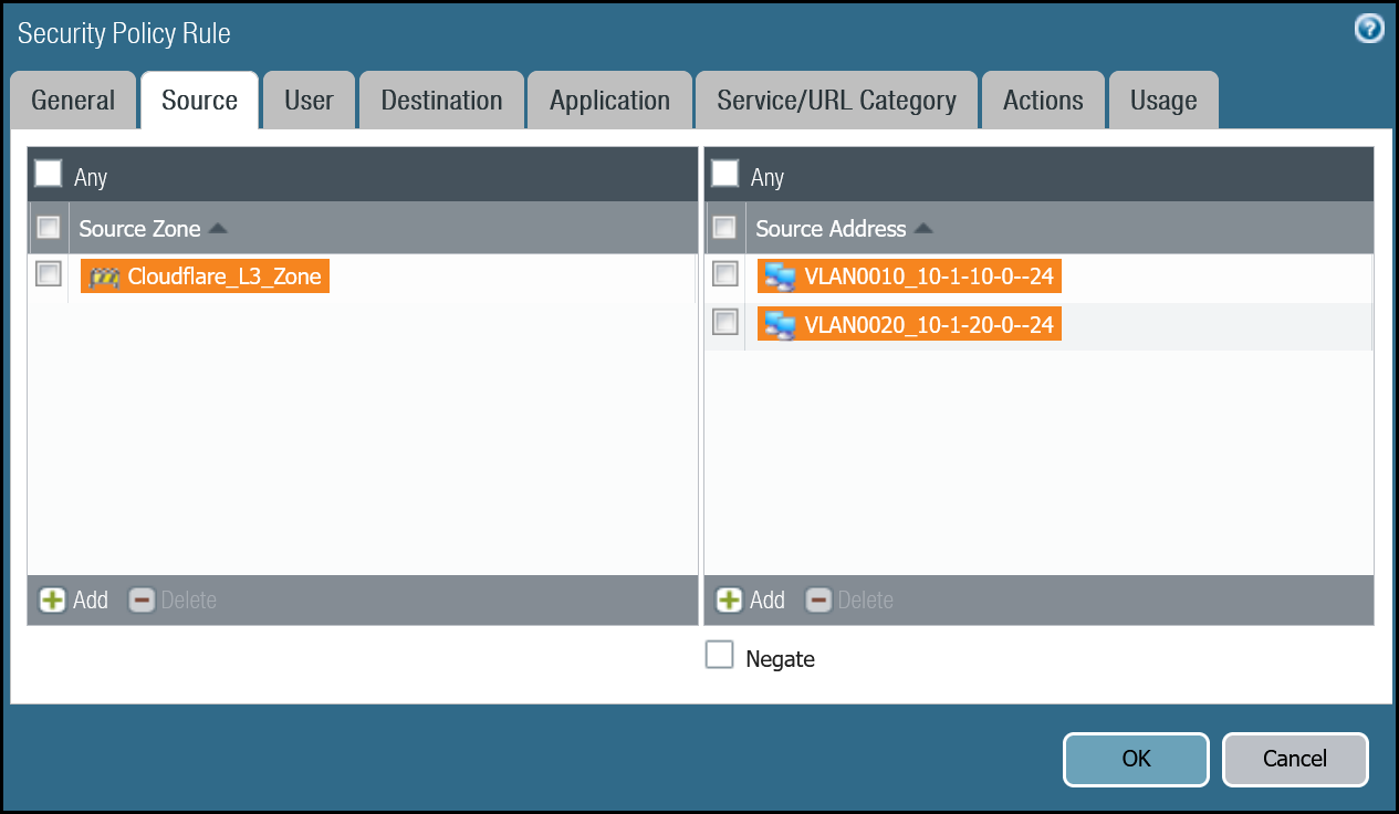
| Source tab | Source Zone | Cloudflare_L3_Zone |
| Source Address | VLAN0010_10-1-10-0–24 VLAN0020_10-1-20-0–24 |
|
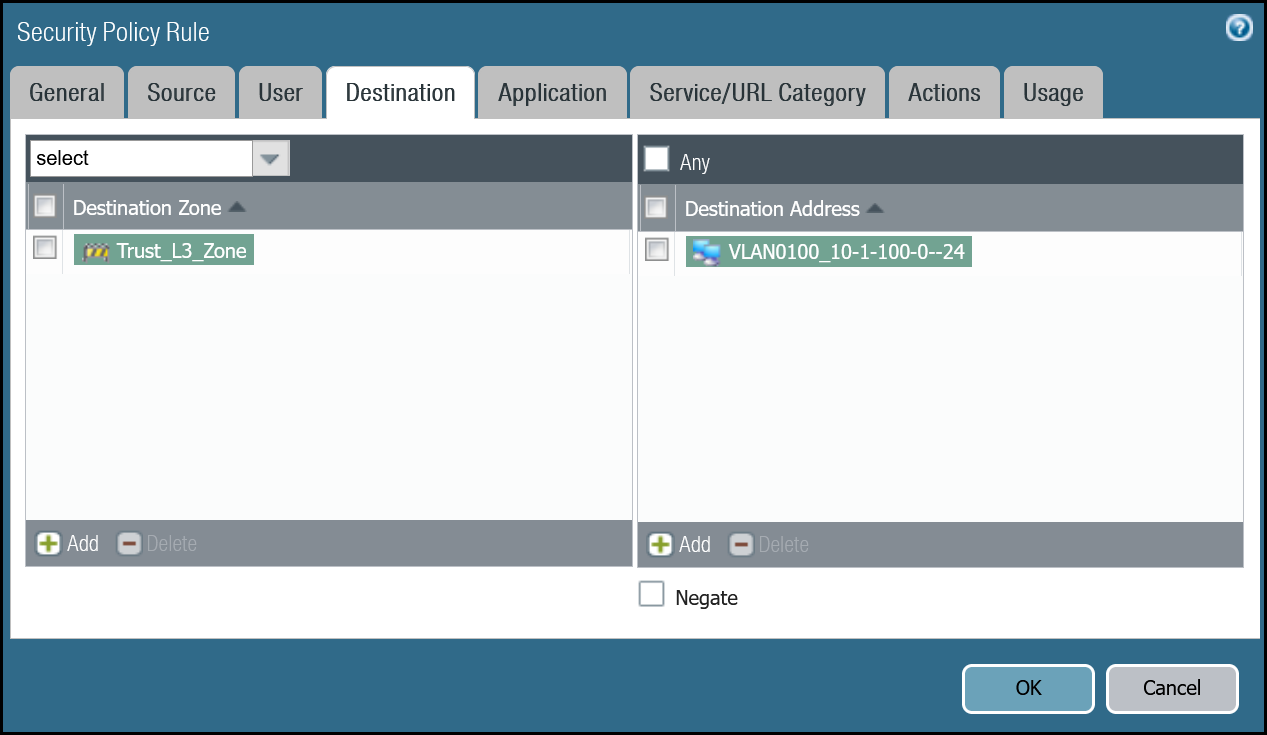
| Destination tab | Destination Zone | Trust_L3_Zone |
| Destination Address | VLAN0100_10-1-100-0–24 | |
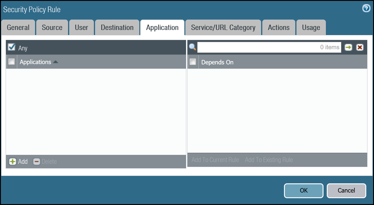
| Actions tab | Action | Allow |
| Log Setting | Log at Session End | |
| Profile type | None | |
| Schedule | None | |
| QoS Marking | None |
Magic WAN to Trust command line
Policy-based forwarding - production traffic
Whether traffic ingresses or egresses Palo Alto Networks Next-Generation Firewall, it is important to ensure that traffic is routed symmetrically. This is accomplished through the use of policy-based forwarding.
Policy-based forwarding rules are only required for egress traffic.
Any traffic destined for Magic WAN protected sites or Magic WAN protected sites with Gateway egress must be routed across the IPsec tunnels.
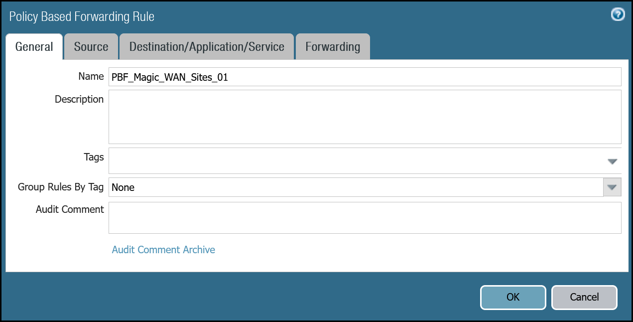
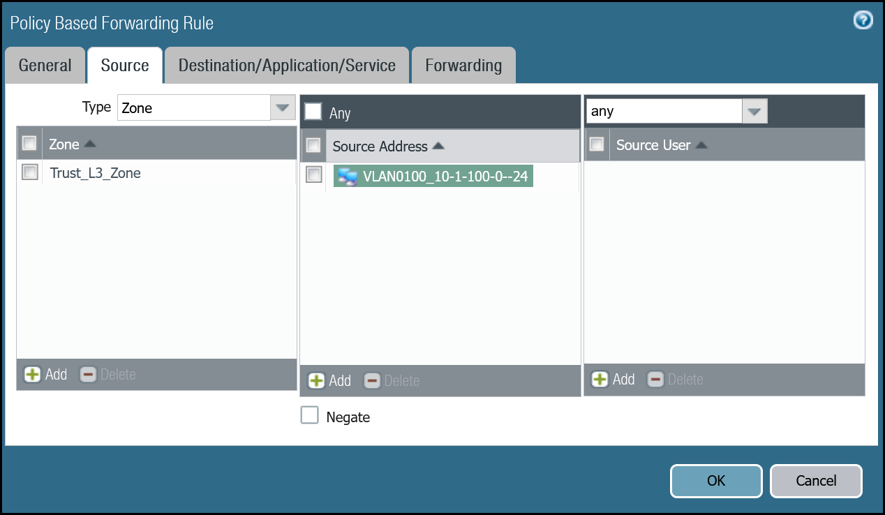
Dashboard policy-based forwarding - Magic WAN production traffic via tunnel.1
| Name | Option | Value |
|---|---|---|
PBF_Magic_WAN_Sites_01 |
Group Rules by Tag | None |
| Source tab | Type | Zone |
| Zone | Trust_L3_Zone | |
| Source Address | VLAN0100_10-1-100-0–24 | |
| Destination/Application/Service tab | Destination Address | VLAN0010_10-1-10-0–24 VLAN0020_10-1-20-0–24 |
| Forwarding tab | Action | Forward |
| Egress Interface | tunnel.1 | |
| Next hop | IP Address | |
| CF_MWAN_IPsec_VTI_01_Remote |
Command line policy-based forwarding - Magic WAN production traffic via tunnel.1
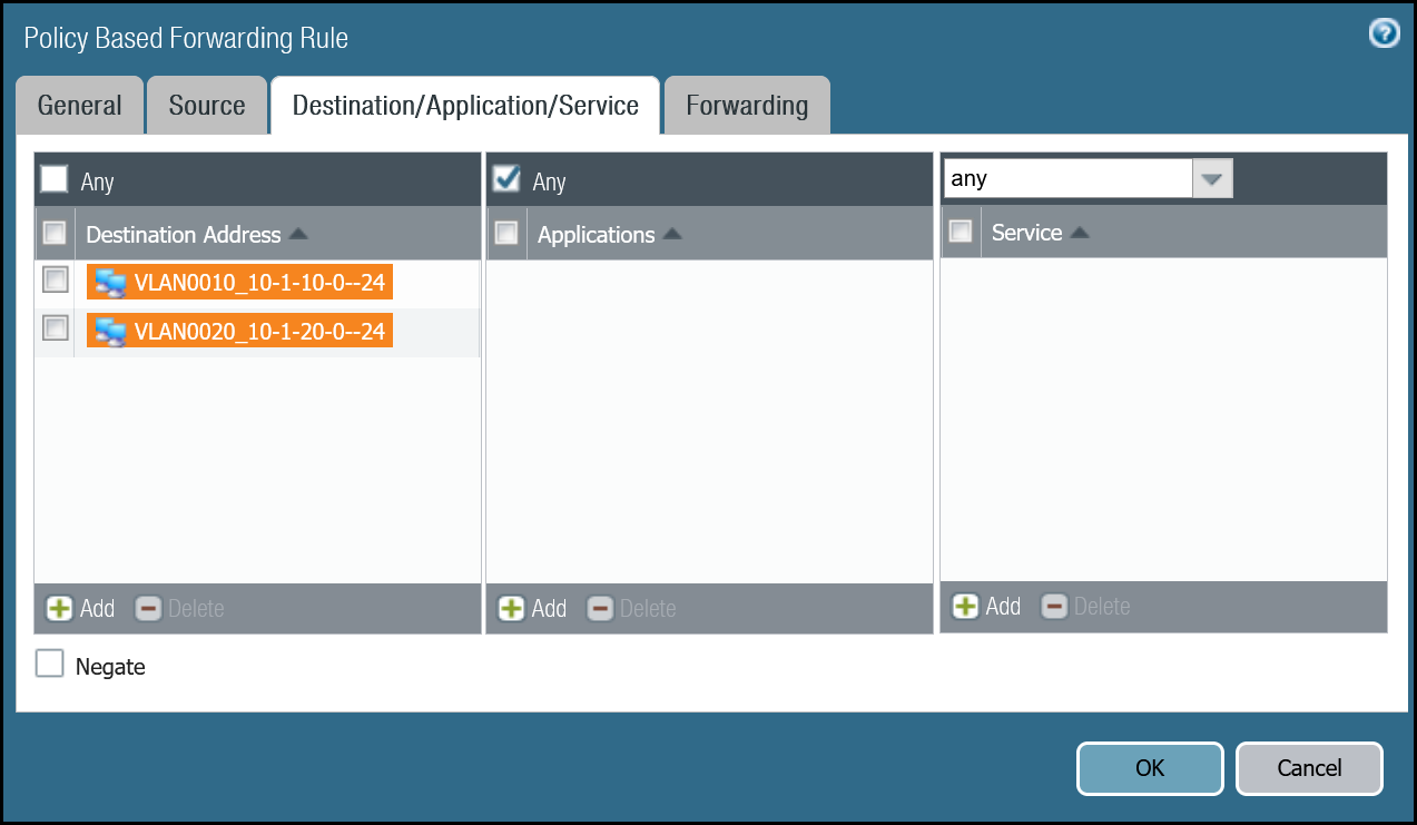
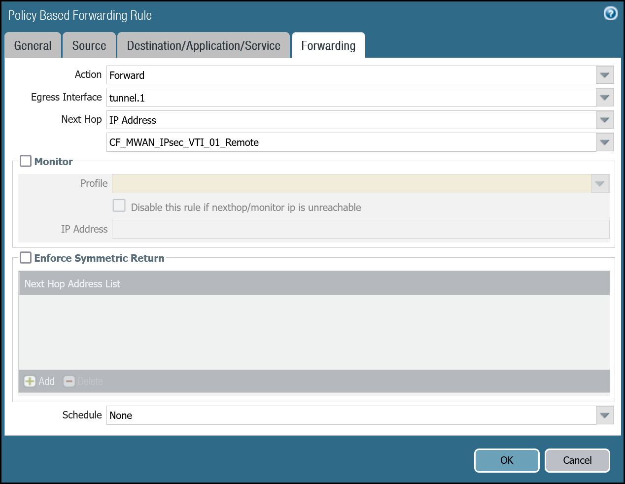
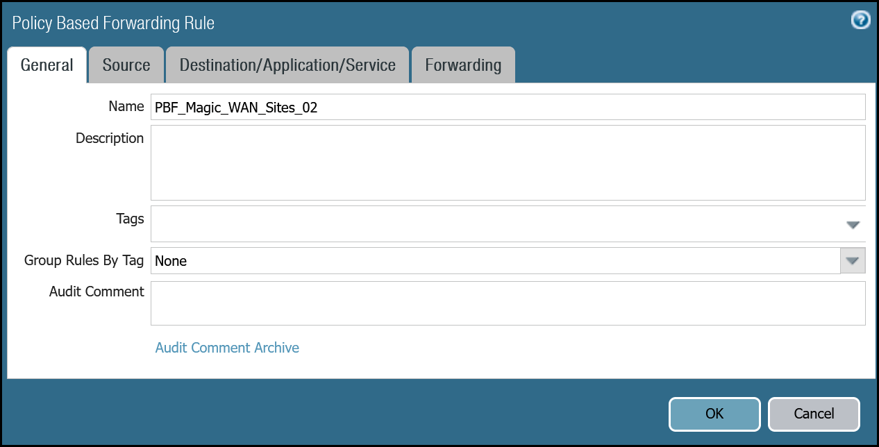
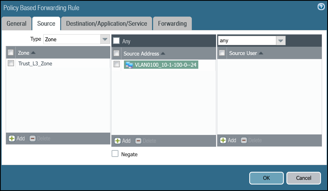
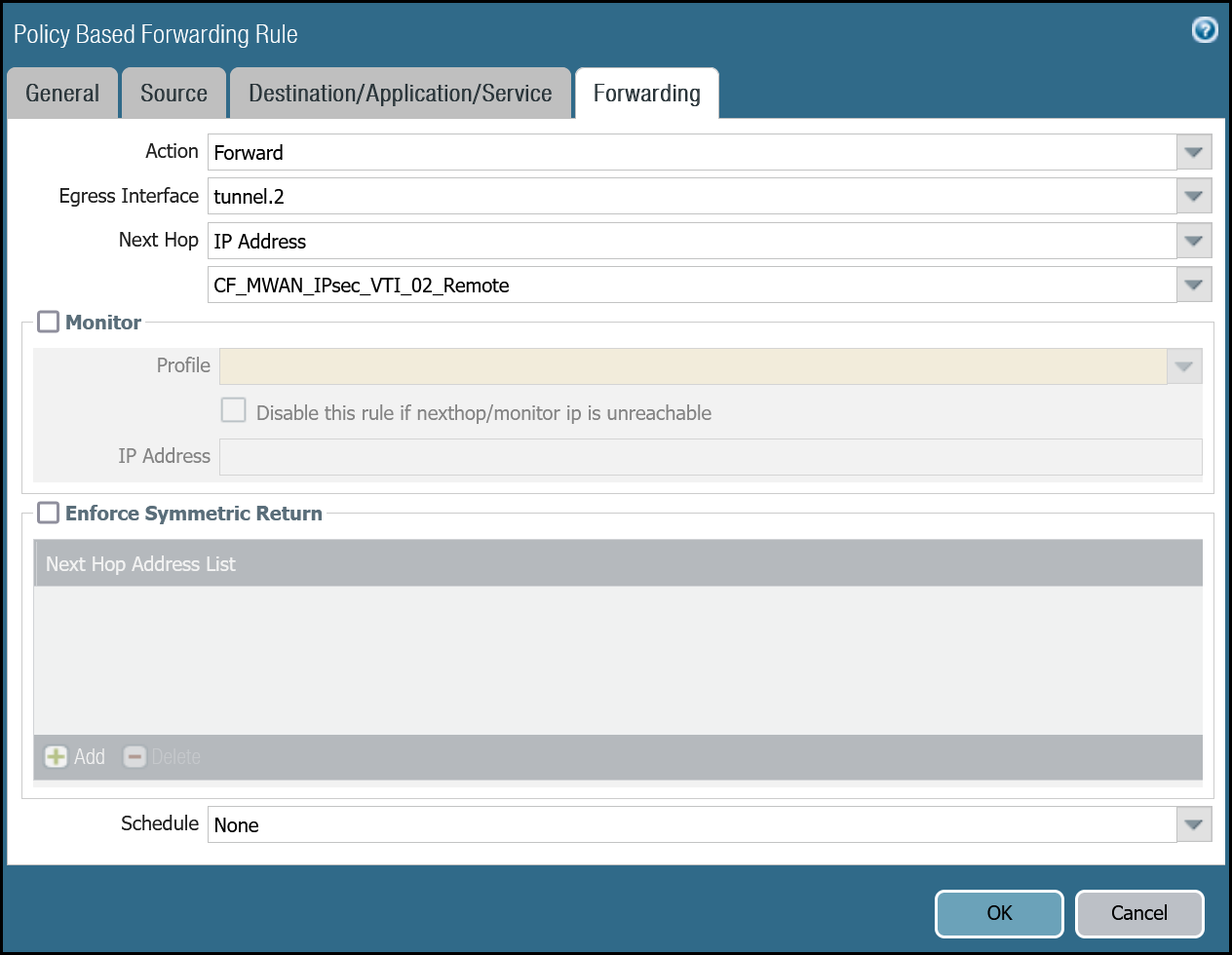
Dashboard policy-based forwarding - Magic WAN production traffic via tunnel.2
| Name | Option | Value |
|---|---|---|
PBF_Magic_WAN_sites_02 |
Group Rules by Tag | None |
| Source tab | Type | Zone |
| Zone | Trust_L3_Zone | |
| Source Address | VLAN0100_10-1-100-0–24 | |
| Destination/Application/Service tab | Destination Address | VLAN0010_10-1-10-0–24 VLAN0020_10-1-20-0–24 |
| Forwarding tab | Action | Forward |
| Egress Interface | tunnel.2 | |
| Next hop | IP Address | |
| CF_MWAN_IPsec_VTI_02_Remote |
Command line policy-based forwarding - tunnel.2
Magic WAN with Cloudflare Zero Trust (Gateway egress)
This section covers adding in support for the use of Cloudflare Gateway. Adding Cloudflare Gateway allows you to set up policies to inspect outbound traffic to the Internet through DNS, network, HTTP and egress filtering.
This use case can be supported in one of two ways:
-
Option 1
- Security Rule: Extend the scope of the
Trust_to_Cloudflare_Magic_WAN_Allowrule to allow any destination address. - Policy-Based Forwarding: Extend the scope of
PBF_Magic_WAN_Sites_01andPBF_Magic_WAN_Sites_02to allow any destination address.
- Security Rule: Extend the scope of the
-
Option 2
- Security Rule: Add a new rule below
Trust_to_Cloudflare_Magic_WAN_AllowcalledTrust_to_MWAN_Gateway_Egress_Allowto allow traffic to any destination address except for the Magic WAN Protected Sites (using the Negate option). - Policy-Based Forwarding: Add a new rule below
PBF_Magic_WAN_Sites_01andPBF_Magic_WAN_Sites_02to allow any destination address except for the Magic WAN Protected Sites (using the Negate option).
- Security Rule: Add a new rule below
The following examples are based on Option 2.
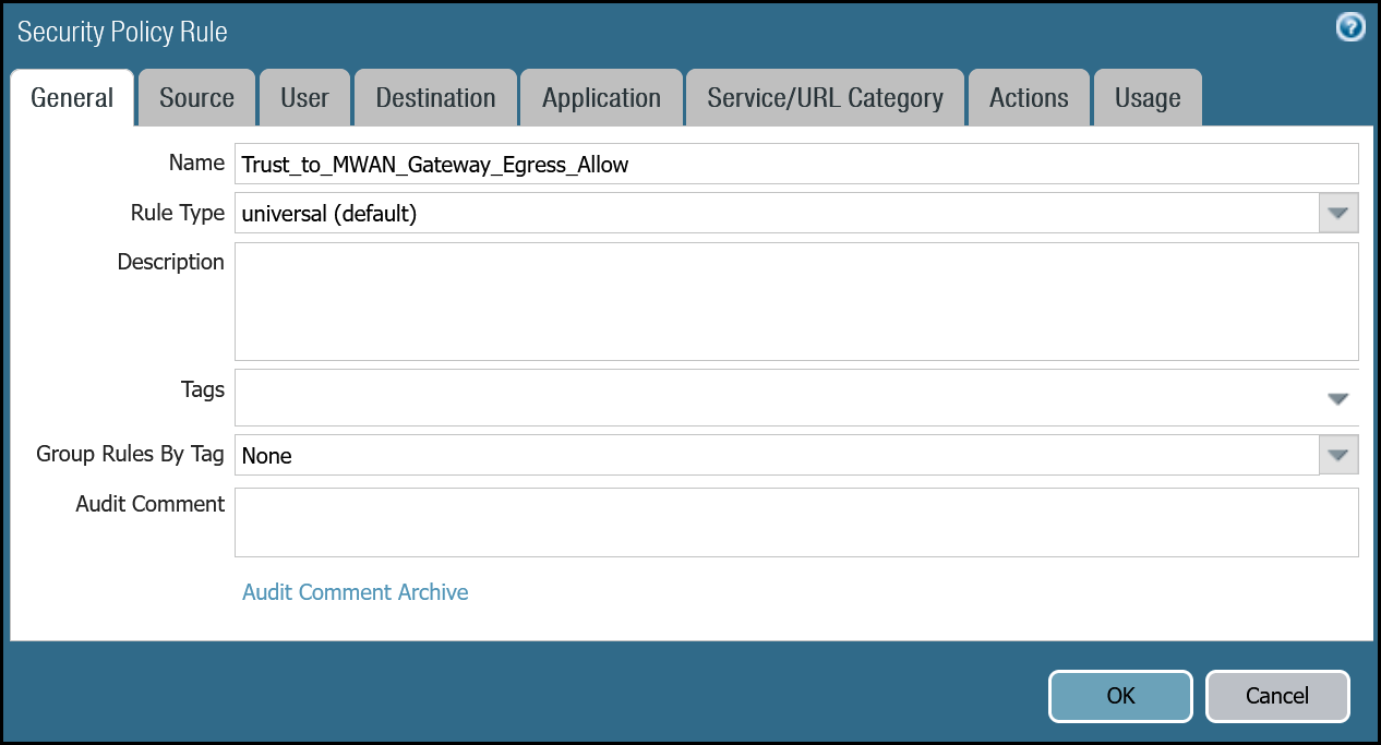
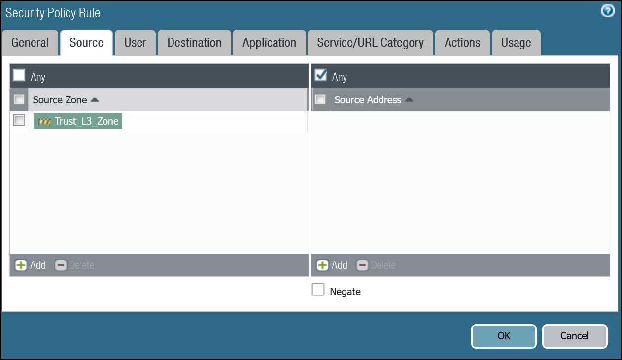
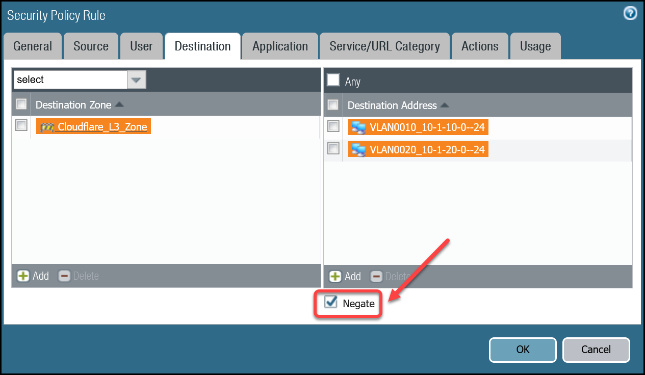
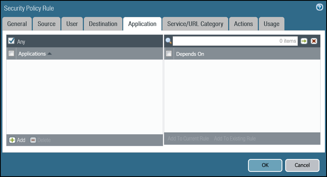
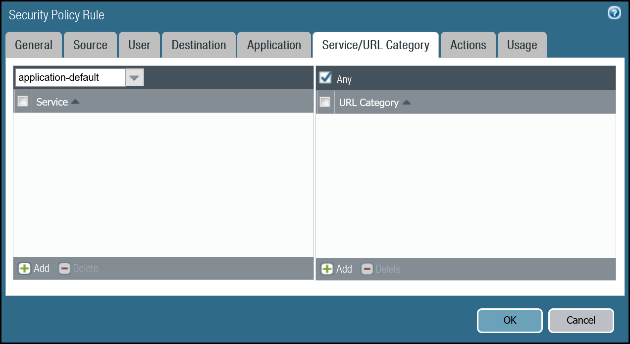
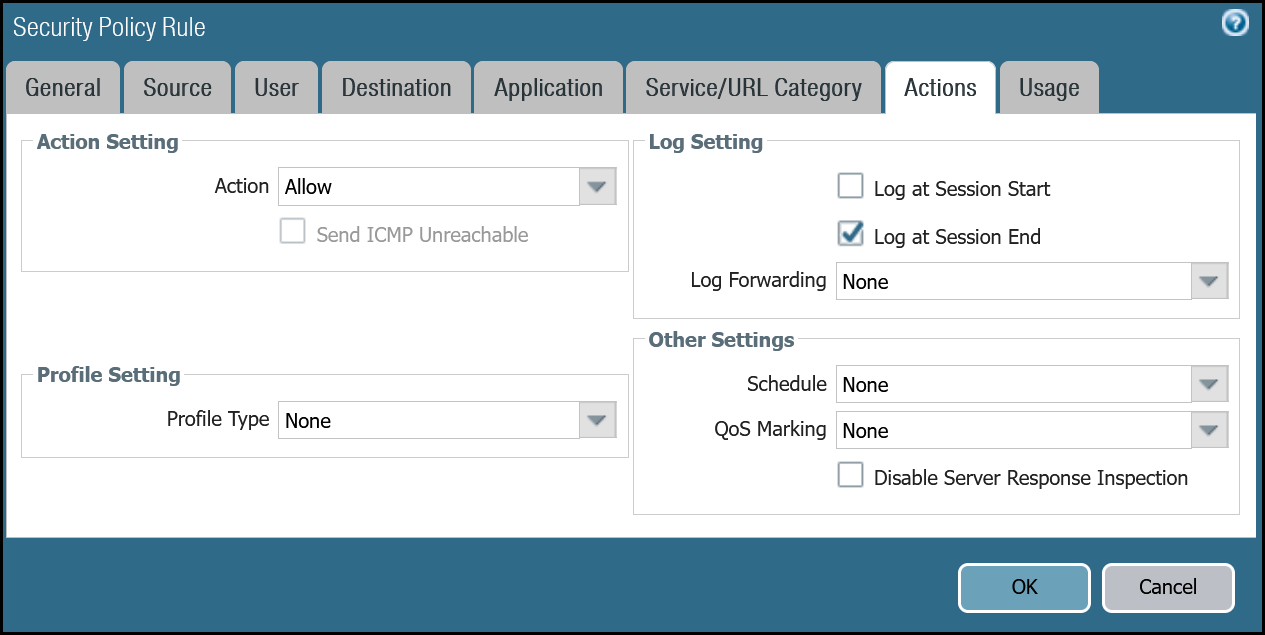
Security Rule: Trust to Gateway Egress
Dashboard
| Name | Option | Value |
|---|---|---|
Trust_to_MWAN_Gateway_Egress_Allow |
Rule Type | universal (default) |
| Group Rules By Tag | None | |
| Source tab | Source Zone | Trust_L3_Zone |
| Destination tab | Destination Zone | Cloudflare_L3_Zone |
| Destination Address | VLAN0010_10-1-10-0–24 VLAN0020_10-1-20-0–24 Negate |
|
| Actions tab | Action | Allow |
| Log Setting | Log at Session End | |
| Profile Type | None | |
| Schedule | None | |
| QoS Marking | None |
Command line
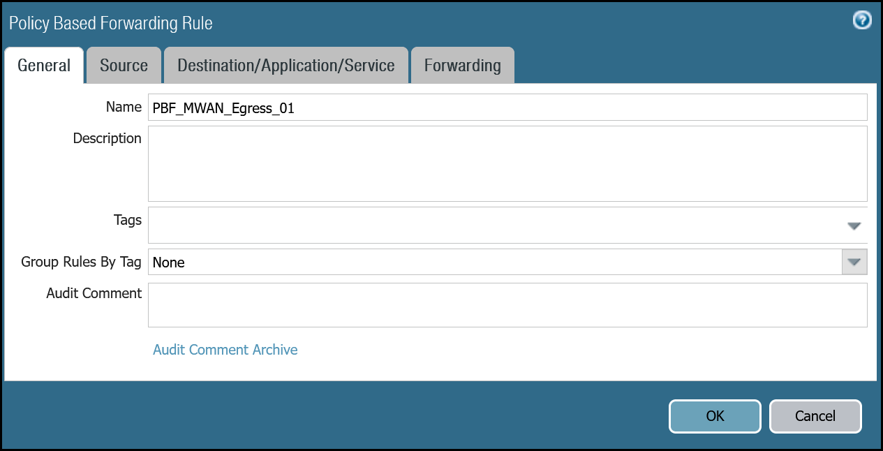
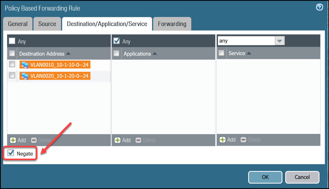
Policy-based forwarding: Trust to Gateway egress via tunnel.1
Dashboard
| Name | Option | Value |
|---|---|---|
PBF_MWAN_Egress01 |
Group Rules By Tag | None |
| Source tab | Source Zone | Trust_L3_Zone |
| Destination/Application/Service tab | Destination Address | VLAN0010_10-1-10-0–24 VLAN0020_10-1-20-0–24 Negate |
| Forwarding tab | Action | Forward |
| Egress Interface | tunnel.1 | |
| Next Hop | IP Address | |
| CF_MWAN_IPsec_VTI_01_Remote |

Command line
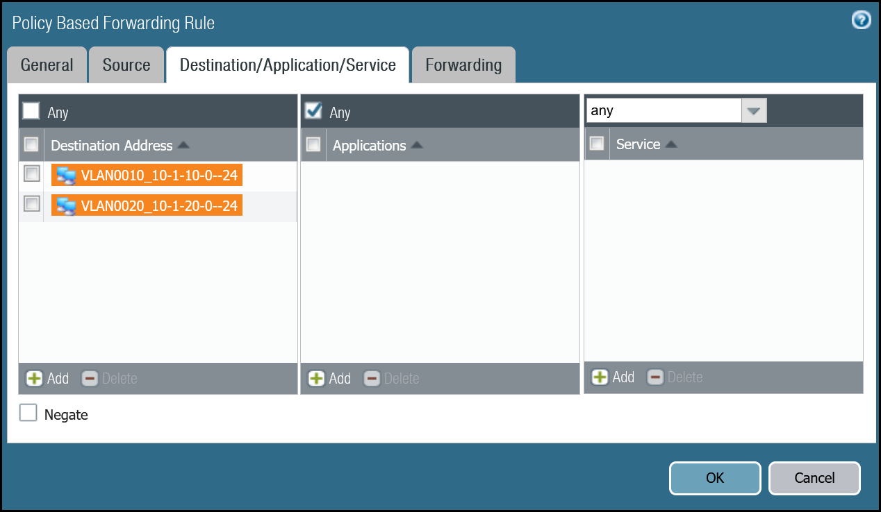
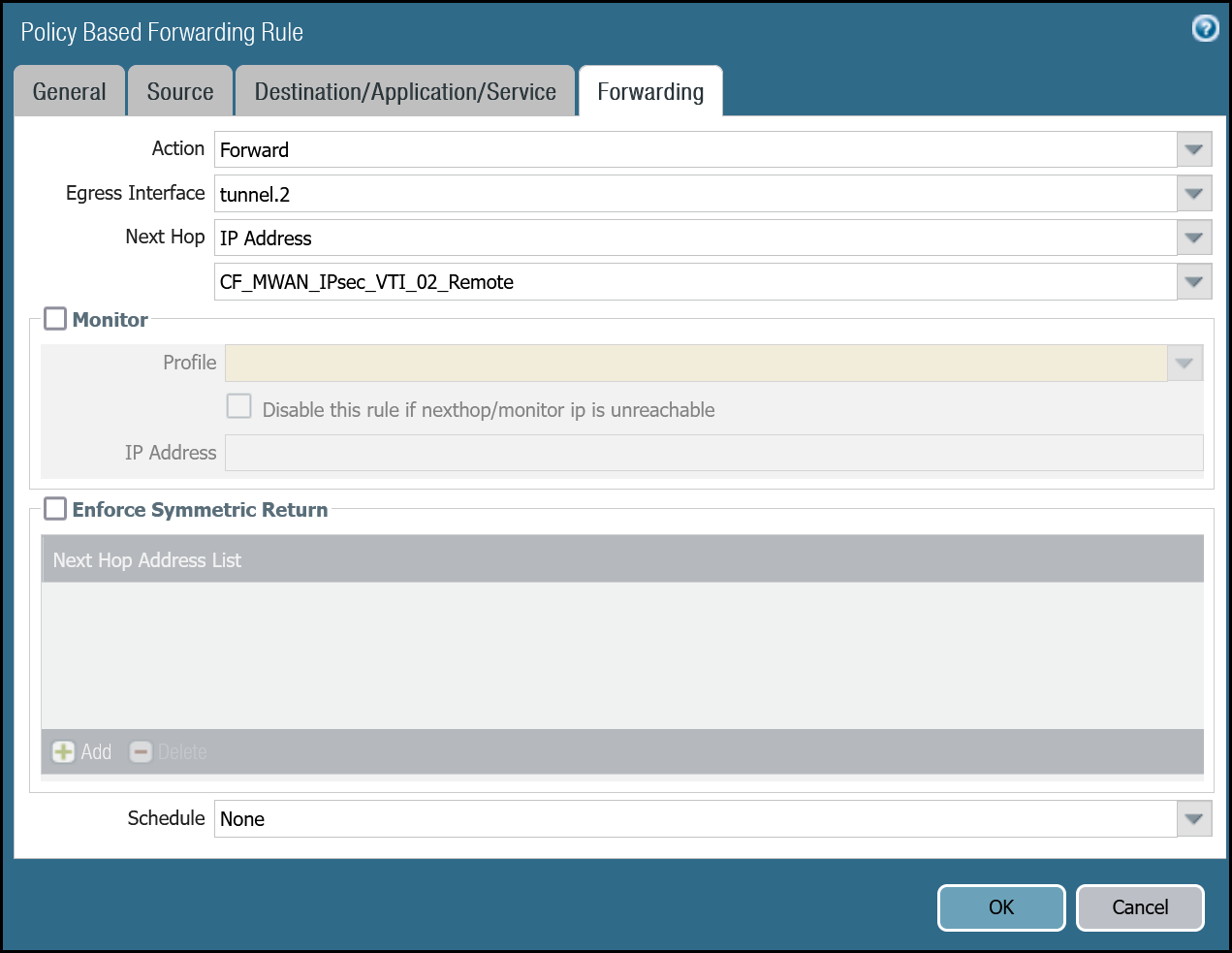
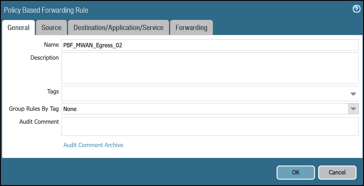
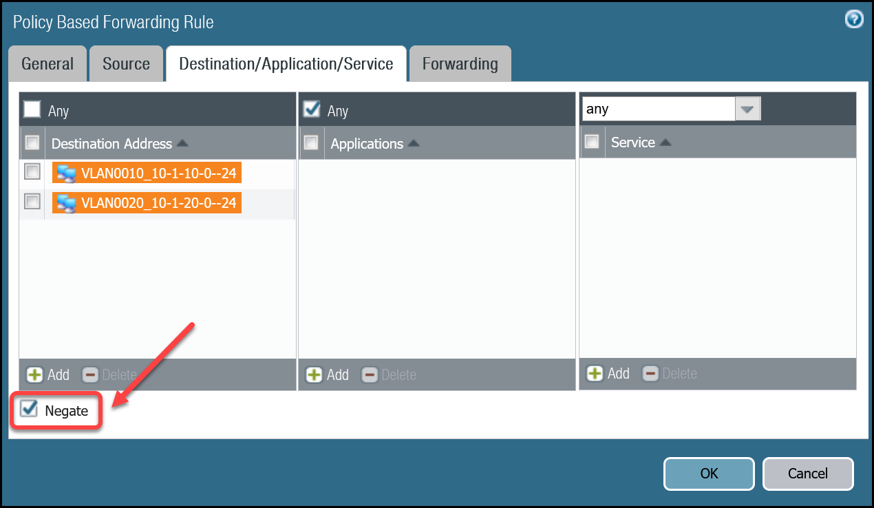
Policy-based forwarding: Trust to Gateway egress via tunnel.2
Dashboard
| Name | Option | Value |
|---|---|---|
PBF_MWAN_Egress02 |
Group Rules By Tag | None |
| Source tab | Source Zone | Trust_L3_Zone |
| Source Address | VLAN0100_10-1-100-0–24 | |
| Destination/Application/Service tab | Destination Address | VLAN0010_10-1-10-0–24 VLAN0020_10-1-20-0–24 Negate |
| Forwarding tab | Action | Forward |
| Egress Interface | tunnel.2 | |
| Next Hop | IP Address | |
| CF_MWAN_IPsec_VTI_02_Remote |

Command line
Troubleshooting
Cloudflare recommends you consult PAN-OS 9.1 Administrators Guide - Interpret VPN Error Messages and PAN-OS 10.2 Administrators Guide - Interpret VPN Error Messages for general troubleshooting.